Sub-pixel Dithers

Sub-pixel dither patterns (SUB) introduce small, sub-pixel offsets between exposures to improve spatial sampling and PSF reconstruction. These patterns do not require large telescope slews.
Sub-pixel dither patterns (SUB) are small-scale offsets that do not require guide star re-acquisition. They are designed to improve sub-pixel sampling and point-spread function (PSF) reconstruction. The Roman WFI sub-pixel dithers are based on the JWST/NIRCam small-grid patterns, re-scaled to the WFI plate scale of 0.11 arcsec/pixel, and further refined using the Roman geometric distortion model. This new distortion-aware approach improves pixel-phase coherence across the focal plane.
The positions for the eight SUB dither patterns are shown in the Figures of Sub-pixel Dither Patterns.
Updates Anticiapted
The sub-pixel dither patterns are being revised. This article will be updated as soon as more details about the sub-pixel dither patterns are determined.
Figures of Sub-pixel Dither Patterns
Below are Roman WFI sub-pixel (SUB) dither patterns, optimized using the WFI distortion model with 10×10 global tie points. Eight different sub-pixel dither patterns are available. The list of sub-pixel dither patterns is provided below:
Changes to the technical details and other specifications presented here are expected as a part of pre-launch development. This includes modifications to the Dither patterns.
Figure of SUB2
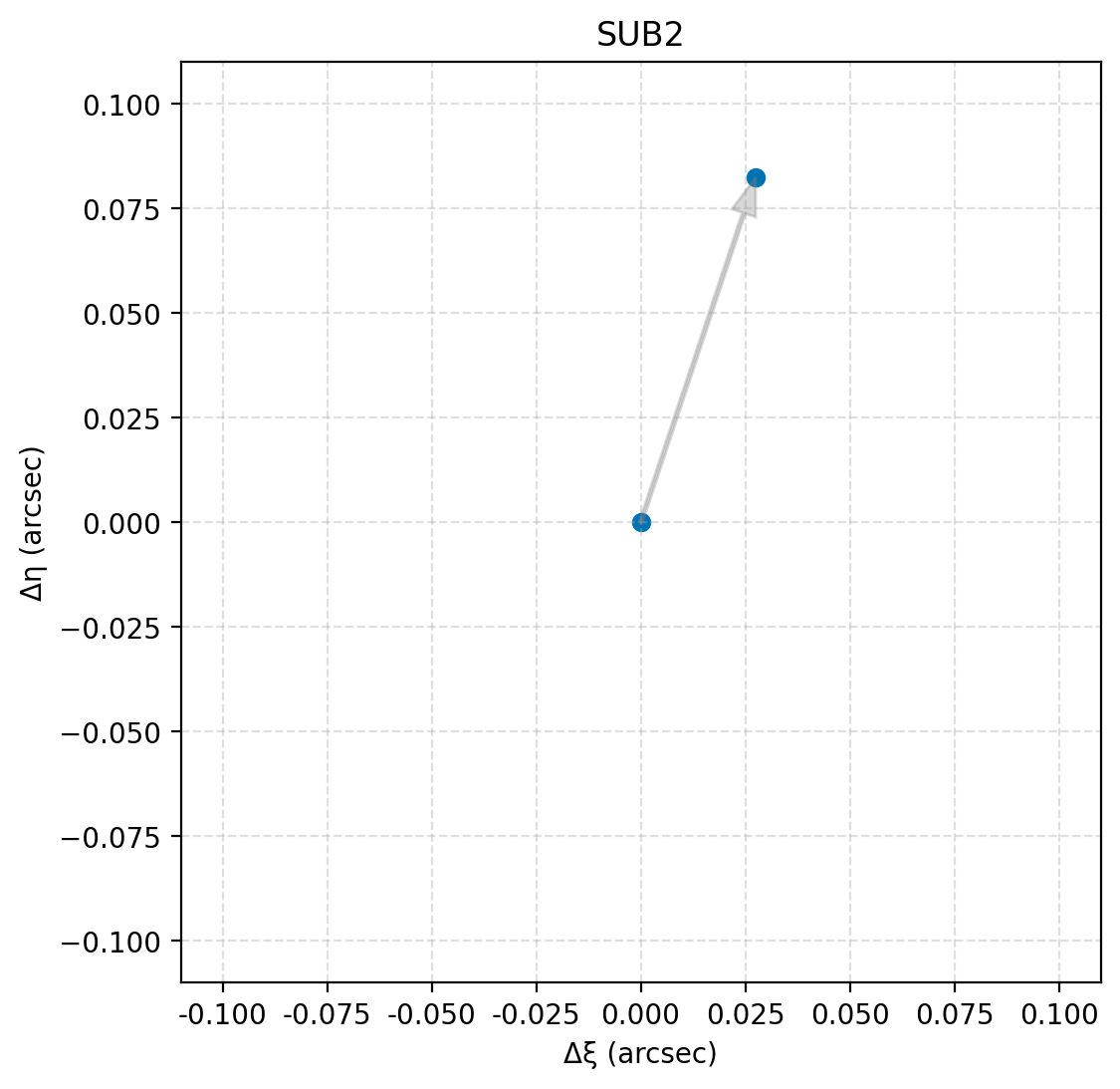
Visualization of the SUB2 sub-pixel dither pattern. Each point represents a subpixel offset in arcseconds, with gray arrows indicating the chronological order of exposures within a dither pattern. The optimized sequence improves pixel-phase coverage and uniformity across the focal plane.
Figure of SUB3
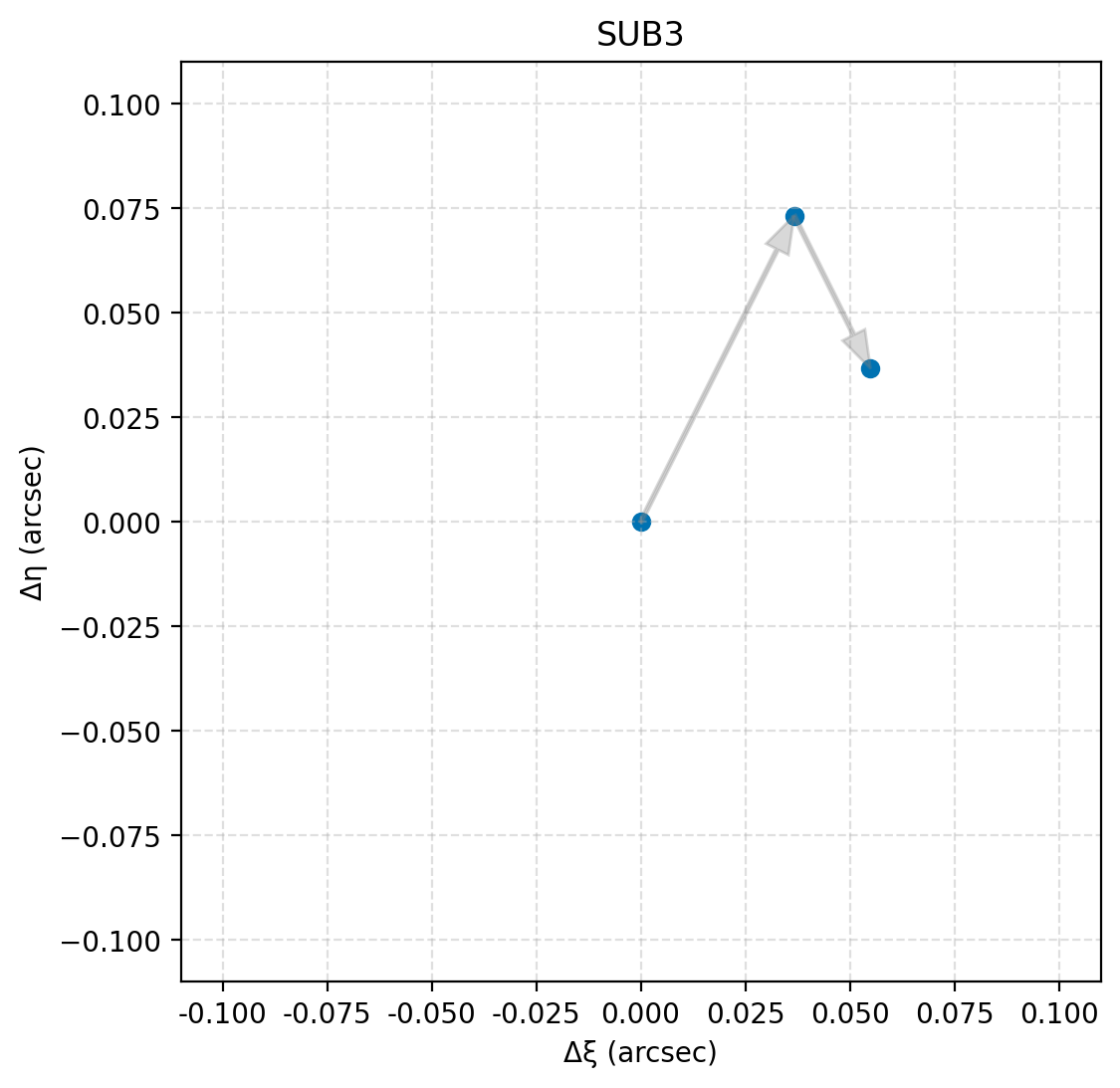
Visualization of the SUB3 sub-pixel dither pattern. Each point represents a subpixel offset in arcseconds, with gray arrows indicating the chronological order of exposures within a dither pattern. The optimized sequence improves pixel-phase coverage and uniformity across the focal plane.
Figure of SUB4
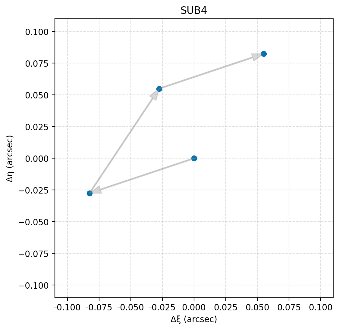
Visualization of the SUB4 sub-pixel dither pattern. Each point represents a subpixel offset in arcseconds, with gray arrows indicating the chronological order of exposures within a dither pattern. The optimized sequence improves pixel-phase coverage and uniformity across the focal plane.
Figure of SUB5
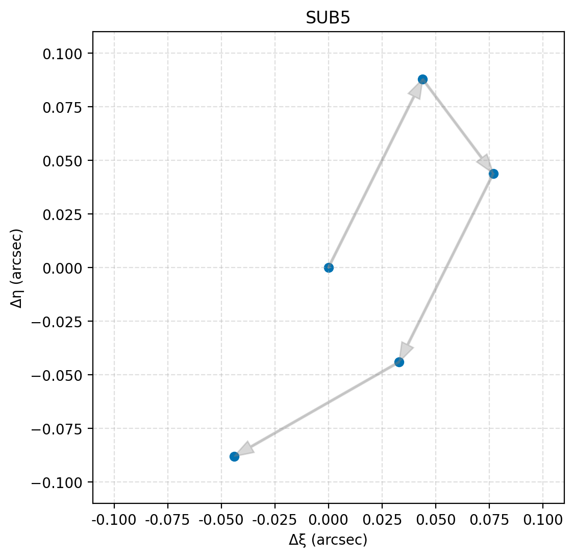
Visualization of the SUB5 sub-pixel dither pattern. Each point represents a subpixel offset in arcseconds, with gray arrows indicating the chronological order of exposures within a dither pattern. The optimized sequence improves pixel-phase coverage and uniformity across the focal plane.
Figure of SUB6
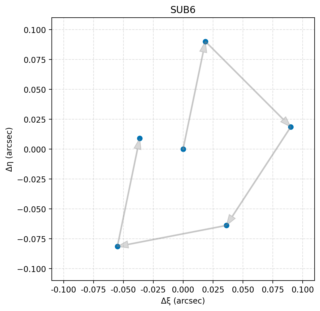
Visualization of the SUB6 sub-pixel dither pattern. Each point represents a subpixel offset in arcseconds, with gray arrows indicating the chronological order of exposures within a dither pattern. The optimized sequence improves pixel-phase coverage and uniformity across the focal plane.
Figure of SUB7
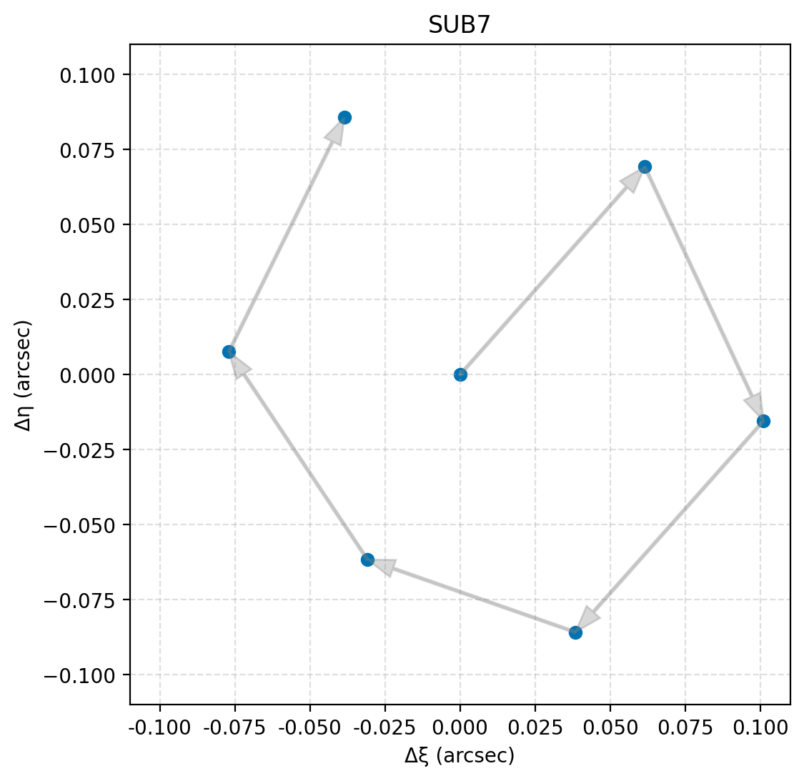
Visualization of the SUB7 sub-pixel dither pattern. Each point represents a subpixel offset in arcseconds, with gray arrows indicating the chronological order of exposures within a dither pattern. The optimized sequence improves pixel-phase coverage and uniformity across the focal plane.
Figure of SUB8
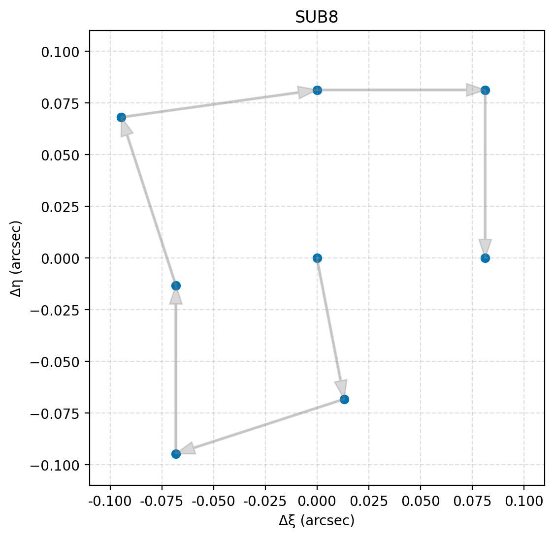
Visualization of the SUB8 sub-pixel dither pattern. Each point represents a subpixel offset in arcseconds, with gray arrows indicating the chronological order of exposures within a dither pattern. The optimized sequence improves pixel-phase coverage and uniformity across the focal plane.
Figure of SUB9
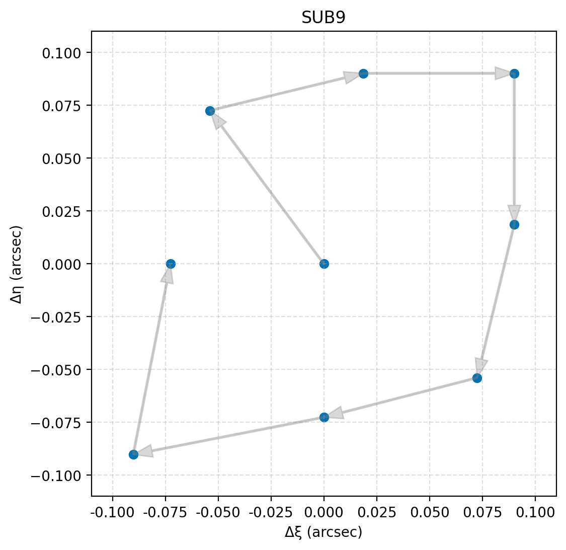
Visualization of the SUB9 sub-pixel dither pattern. Each point represents a subpixel offset in arcseconds, with gray arrows indicating the chronological order of exposures within a dither pattern. The optimized sequence improves pixel-phase coverage and uniformity across the focal plane.
For additional questions not answered in this article, please contact the Roman Help Desk.