Aladin Visualization

Aladin is a visualization tool integrated with APT that allows you to view program targets and instrument apertures displayed on sky images.
Aladin is already in use with APT for HST and JWST programs.
Starting Aladin
To view program elements in Aladin, select one or more program element(s) in APT's left panel, then click the View in Aladin button on the top APT toolbar.
With this version of APT, the program elements you can visualize with Aladin are:
- Fixed Targets
- Region Targets
- Pass Plans
- Selected observations within a Pass Plan
- Survey Steps
Aladin Controls
To control the opacity (shading) of the aperture, use the opacity slider in the lower right panel.
To load background sky images from the Digitized Sky Survey (DSS), click the DSS button on the APT Aladin Controls toolbar.
To load a color full-window DSS image, click the DSS button on the Aladin window (not on the APT Aladin Controls Toolbar). Many other image sources are available within Aladin using File > Load Astronomical Image.
- To adjust the image, use the Pixel tool in the right panel of the Aladin window.
To zoom in or out, do one of the following:
- Use the mouse wheel
- Use the Zoom slider on the lower right panel
- Click the 'Z' tool on the vertical toolbar - a highlighted square appears. Drag the highlighted square over the image, then click to zoom in, or shift-click to zoom out.
To re-center the view at a default zoom level, click anywhere in the inset square on the lower right panel.
Managing Level of Detail
APT performance can be greatly slowed down when Aladin displays complex programs. For that reason, APT provides several ways to control the level of detail displayed.
- Single Aperture button (on the APT Aladin Controls toolbar). Displays the outline of each full WFI footprint in the selection, without showing the 18 individual detectors (see Simple Pass Plan).
- Single Mosaic button (on the APT Aladin Controls toolbar). Displays the approximate outline of each mosaic footprint with no internal detail (see Pass Plan with Mosaic).
- Automatically reduce detail. APT provides an option to automatically reduce the level of detail Aladin displays when a selection is too complex to display in an acceptable amount of time. This option is "Automatically adapt level of detail for Roman observations" and is available in the View in Aladin menu (under the Aladin Display sub-menu). This option is enabled by default but may be turned off by the user.
- Select one or more observations in a Pass Plan to display only those observations (instead of selecting the entire Pass Plan).
When viewing a Survey Step, APT reduces the level of detail shown on the individual pass plans, and the Single Aperture button and Single Mosaic button have no effect. This is done to ensure acceptable performance of APT and Aladin.
View Pass Plans in Aladin
To view a Pass Plan in Aladin, select a Pass Plan in the left panel, then click the View in Aladin button.
All pass plans of fixed targets are currently displayed at a default V3PA orientation of 0 degrees. You can manually rotate the display in Aladin to explore other orientations. Pass plans of region targets are displayed at the Planned Orient by default.
Simple Pass Plan
Figure of a Simple Pass Plan


This pass plan shows a simple pass with the characteristic "batwing" footprint of the WFI aperture. Note that there are gaps between the 18 detectors which can be covered by using dithers. However, no dithering is used in this example, and only a single WFI aperture is shown. The image on the right shows the same pass but with Single Aperture selected so individual detectors are not shown, although the gaps between detectors are still present.
Simple Pass Plan with Dithers
Figure of a Simple Pass Plan with Dithers
This Pass Plan adds a 4-point dither (BOXGAP4_1) to cover the gaps between detectors.
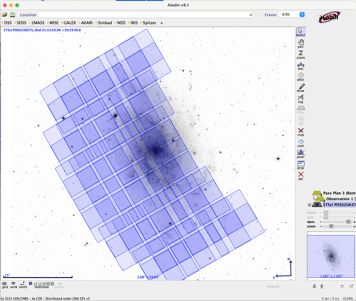
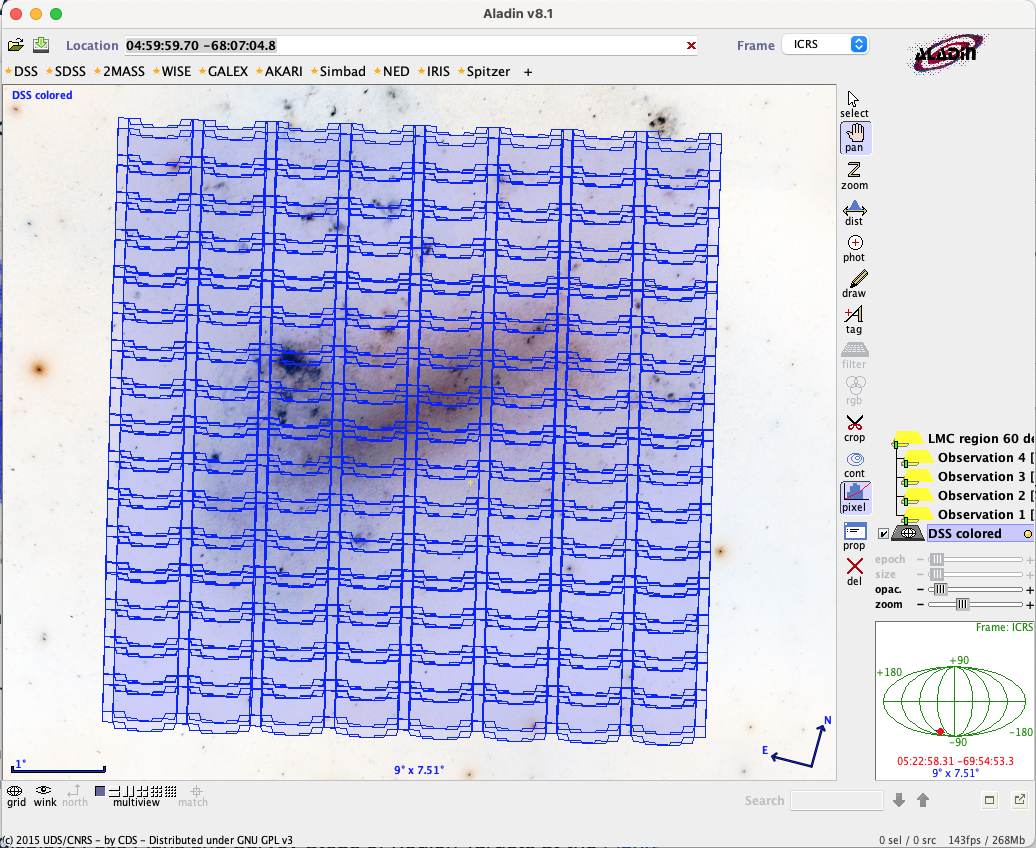
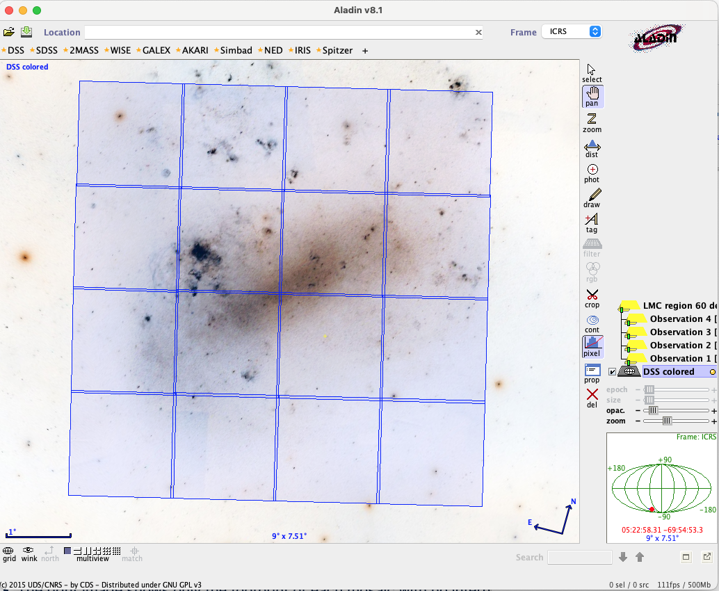
Pass Plan with Mosaic
Figure of a Pass Plan with a 2x1 Mosaic
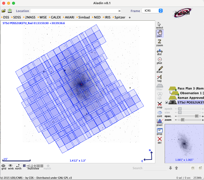
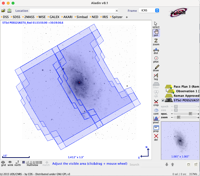
Pass Plan with 2x1 mosaic and a 4-point dither (BOXGAP4_1). The level of detail shown may be controlled with the Single Aperture and the Single Mosaic button (from Roman Demonstration Program 960). Each image shows the same mosaic at a different level of detail:
- The first image shows the outline of each detector (Single Aperture and Single Mosaic both off).
- The second image shows each tile in the mosaic but not each detector (Single Aperture on, Single Mosaic off).
- The last image shows the footprint of the entire mosaic with no internal detail (Single Mosaic on). Note that the outer perimeter is displayed as an approximation and should be checked at a higher level of detail.
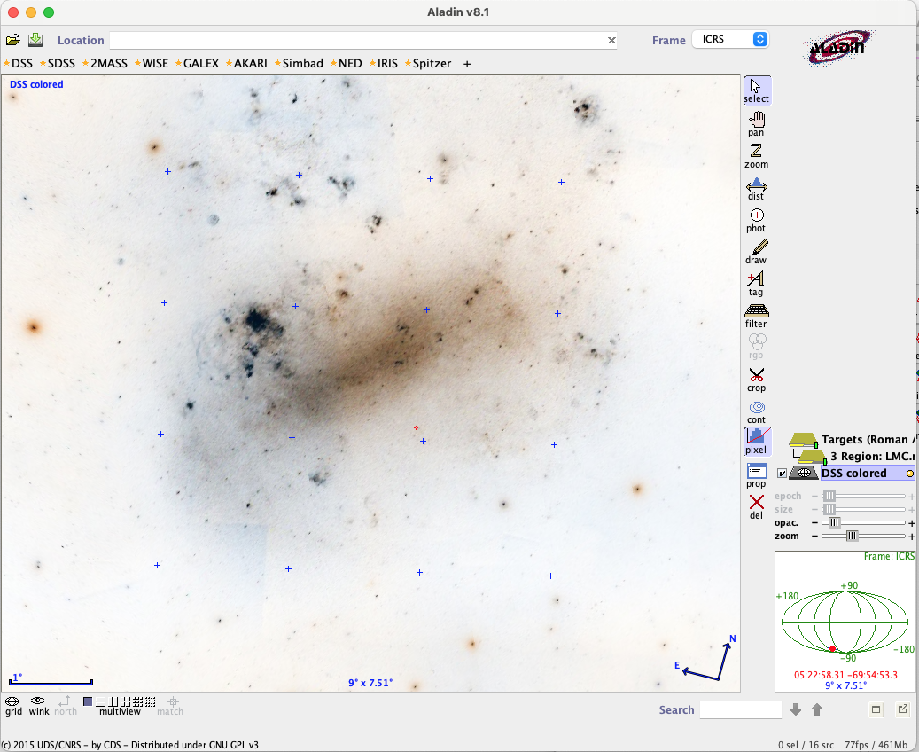
Pass Plan with Region Target
Figure of a Pass Plan with a Region Target
 .
. 
This Pass Plan uses a Region Target with 16 points to cover the Large Magellanic Cloud. Each point in the region is covered by a 4x2 mosaic (from Roman Demonstration Program 961).
Both images show the same Pass Plan at a different level of detail:
- The first image shows the tiles inside each of the 16 mosaics (Single Mosaic off).
- The second image shows only the footprint of each mosaic with no internal detail (Single Mosaic on).
Aladin displays Pass Plans and Survey Steps of Region Targets at the Planned V3PA. For Fixed Targets, Survey Steps are displayed at the center of the V3PA Range.
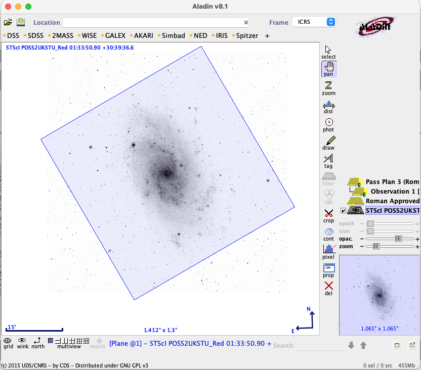
View Targets in Aladin
To view a target in Aladin, select a target in the left panel, then click the View in Aladin button.
- For a fixed target, Aladin displays a small blue reticle (resembling a plus sign) for the target coordinates.
- For a region target, Aladin displays a reticle at the fiducial point of each of the coordinates in the target.
Figure showing Region Target in Aladin
In this example, Aladin displays a Region Target with 16 points, with a small blue reticle (plus sign) at each point.
For additional questions not answered in this article, please contact the Roman Help Desk.