Mosaic Patterns

A Mosaic Pattern is a specification in APT of a sequence of offsets for mosaicking a Roman Observation. The Mosaic Plan is built in the Mosaic Pattern Form.
Mosaic Pattern Overview
Mosaic patterns are created by entering the number of rows and columns on the Mosaic Pattern form to build a pattern of identical tiles. A wide range of mosaic shapes may be created by applying row or column shifts, disabling selected tiles, or by using a custom mosaic pattern. A Mosaic Pattern is not specific to a Target and may be used for any Observation (see Pass Plans). All of the Tiles in a Mosaic Pattern are observed at the same orientation.
Figure that Shows the Mosaic Pattern Editor
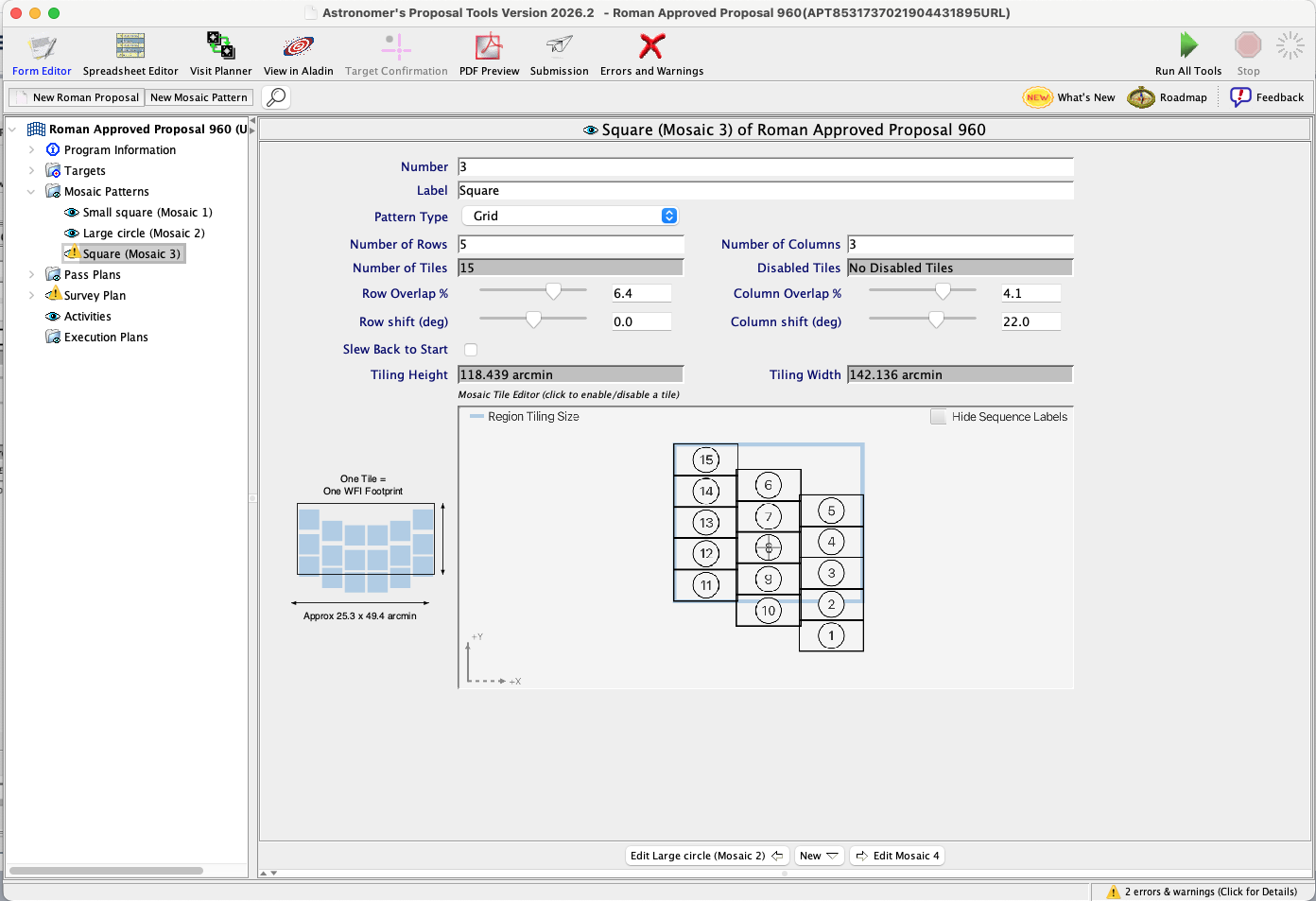
An example 5 Tile by 3 Tile Mosaic Pattern built using the APT Mosaic Pattern form. The size of the mosaic is shown in the Tiling Height and Tiling Width. This mosaic uses a Column Shift of 22%. Each tile (numbered rectangle) represents one WFI footprint, about 25.3 x 49.4 arcmins on the sky. The blue outline rectangle represents interlocking tiles, which is more useful for designing mosaics, e.g. to avoid creating unintended gaps between tiles. The "+" reticle indicates where the target is placed.
Mosaic Plan Parameters
A Mosaic Pattern has the following parameters.
Number
NUMBER
A number that designates the Mosaic Pattern. Required; incremental numbers are added by default but may be changed by the user.
Label
LABEL
A name that identifies the Mosaic Pattern. Not required. The label identifies the Mosaic Pattern in the hierarchical editor and in drop-down lists.
Pattern Type
PATTERN TYPE = GRID (default), CUSTOM
Select the method you want to use to create the mosaic pattern.
- When GRID is selected, a Mosaic Pattern may be created by specifying the number of rows and columns, all tiles having uniform relative offsets.
- When CUSTOM is selected, the Offsets controls become available for defining custom mosaic offsets. Custom Mosaic Patterns allow design of irregular patterns, with each tile having an independent offset from the default pointing.
Offsets
(available only when PATTERN TYPE = CUSTOM )
The Offsets controls provide a table for entering custom mosaic patterns. Each row in the table specifies an X,Y target offset in arcminutes for one tile in the mosaic. Note, the corresponding offset of the aperture is given by (-X,-Y).
- Click Add to enter an X,Y pair of offsets in arcminutes for that tile.
- Click Import to import a mosaic pattern in
csvformat. - Click Export to export the custom mosaic pattern in
csvformat.
Tiles of a Custom Mosaic Pattern are executed in the order entered in the Offsets table.
Number of Rows
(available only when PATTERN TYPE = GRID )
NUMBER OF ROWS
The number of rows in the Mosaic Pattern (required). Default is 1. Allowed range is 1 TO 100 .
Number of Columns
(available only when PATTERN TYPE = GRID )
NUMBER OF COLUMNS
The number of columns in the Mosaic Pattern (required). Default is 1. Allowed range is 1 TO 100 .
Number of Tiles
NUMBER OF TILES
The number of Tiles in the Mosaic Pattern. A maximum of 999 tiles (visits) per observation is allowed. This values is either the number of Offsets in the table or calculated from the Number of Rows x Number of Columns minus any tiles disabled with the Mosaic Tile Editor. For example: for a 5 x 3 pattern, the number of tiles is 15.
Disabled Tiles
(available only when PATTERN TYPE = GRID )
DISABLED TILES
The number of tiles that have been disabled. Tiles may be disabled to exclude them from the mosaic (see Mosaic Tile Editor).
Row Overlap %
(available only when PATTERN TYPE = GRID )
ROW OVERLAP %
The percent overlap for rows (required). Allowed range is -200 to 100 (negative overlap results in sparse coverage).
Column Overlap %
(available only when PATTERN TYPE = GRID )
COLUMN OVERLAP %
The percent overlap for columns (required). Allowed range is -200 to 100 (negative overlap results in sparse coverage).
Row Shift (deg)
(available only when PATTERN TYPE = GRID )
ROW SHIFT (DEG)
The shift in degrees for rows (required). Default is 0 degrees. Allowed range is -90 to 90 . Note that the shift refers to the angle between the same tile corner on two adjacent rows.
Column Shift (deg)
(available only when PATTERN TYPE = GRID )
COLUMN SHIFT (DEG)
The shift in degrees for columns (required). Default is 0 degrees. Allowed range is -90 to 90 . Note that the shift refers to the angle between the same tile corner on two adjacent columns. See illustration in Mosaic Pattern Overview.
Slew Back to Start
SLEW BACK TO START
Determines the slew order for successive observations.
When SLEW BACK TO START is not selected (default):
- For odd-numbered observations, mosaic tiles are executed in ascending order.
- For even-numbered observations, mosaic tiles are executed in reverse tile order. This prevents a slew from the last tile back to Tile 1 (or the lowest-numbered tile).
When SLEW BACK TO START is selected:
- All observations execute mosaics in ascending tile order. This means that when the last tile is executed, a slew is performed from the last pointing back to the pointing of the lowest-numbered tile for the subsequent observation.
The mosaic execution order described above applies to all observations, even if they use different mosaic patterns.
Tiling Height
TILING HEIGHT
Displays the calculated height of the Mosaic Pattern in arcminutes, taking any overlaps into account. When used in a Region Target, overlap between Segments is initially inherited from the selected Mosaic.
Tiling Width
TILING WIDTH
Displays the calculated width of the Mosaic Pattern in arcminutes, taking any overlaps into account. When used in a Region Target, overlap between Segments is initially inherited from the selected Mosaic.
Mosaic Tile Editor
Mosaic Patterns are created by entering the number of rows and columns on the Mosaic Pattern Form. Once the initial grid is created, the pattern is represented in the Mosaic Tile Editor.
Irregular patterns may be created by applying row or column shifts, and/or disabling one or more tiles. To disable a tile, click it in the Mosaic Tile Editor (click again to enable it). Disabled Tiles are shown with a diagonal line. The Figure that shows the functions of the Mosaic Tile Editor shows an example of removing tiles. Tiles may not be disabled for custom mosaic patterns.
If you change NUMBER OF ROWS or NUMBER OF COLUMNS , a new grid is created with all Tiles enabled.
Sequence labels (numbers) are displayed on each tile by default. To hide sequence labels, select the Hide Sequence Labels checkbox.
The X-Y arrows indicate the X and Y axes in the ideal frame.
Figure that shows the functions of the Mosaic Tile Editor
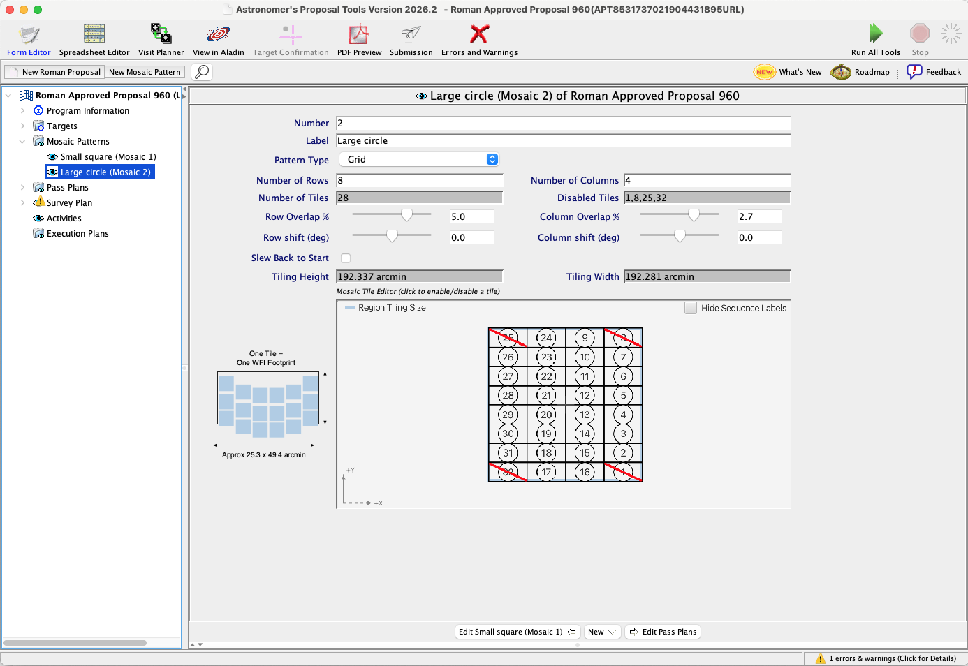
An example Mosaic Pattern that is 32 Tiles in an approximately circular shape built using the APT Mosaic Pattern form. In this case, the default mosaic pattern has been edited using the Mosaic Tile Editor to remove the corners of the rectangular to better fit a circular shape. This visual tool shows how disabled tiles (1, 8, 25, and 32) are marked with a red diagonal line.
For additional questions not answered in this article, please contact the Roman Help Desk.