WFI Dithering

The Nancy Grace Roman Space Telescope's Wide Field Instrument (WFI) supports a predefined set of Dither Patterns. Two classes of dither patterns are available: those designed to fill detector gaps (GAP Dither Patterns) and those that provide sub-pixel sampling (SUB Dither Patterns). The available options for both classes are described in this article.
Dither Pattern Overview
Dither patterns can be used for several purposes, including:
- filling gaps in sky coverage between the 18 WFI detectors,
- mitigating the effects of flat-field uncertainties and scattered light, and
- providing sub-pixel sampling.
Roman WFI dither patterns fall into two categories: GAP dither patterns, which are designed to fill detector gaps, and SUB dither patterns, which provide sub-pixel sampling. This article provides an overview of both types. More detailed information on each category, including guidance on their effective use, is available in the Gap-filling Dithers and Sub-pixel Dithers articles.
Observation Design Hierarchy
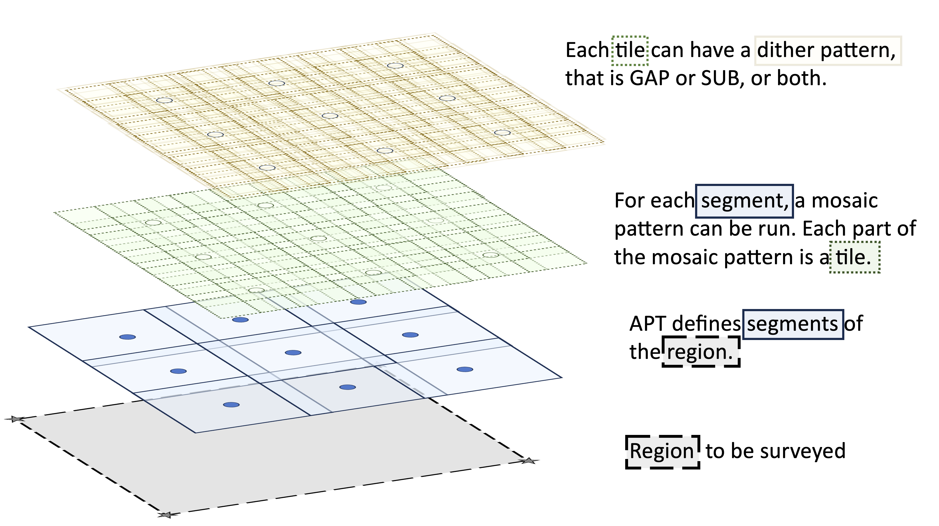
Simplified cartoon demonstrating key terms in the hierarchy of Roman observations.
Dither Patterns in the Observation Hierarchy
The Roman Observation Design Hierarchy Figure illustrates how different layers of an observation are related. For Roman observations, Dither Patterns are executed at the level of a Tile, which corresponds to a single WFI pointing. Tiles are, in turn, executed within user-defined Mosaic Patterns, which together define the overall pointing strategy for a Segment.
WFI dither patterns are selected in the Pass Plans window of the Astronomer's Proposal Tool (APT). GAP Dither Patterns and SUB dither patterns can be used simultaneously; when both are selected, the SUB dither pattern is executed at each pointing of the GAP Dither.
Dither offsets are specified in the WFI Ideal coordinate system and are defined relative to the base pointing of the selected aperture. There are two conventions for specifying offsets with respect to the base pointing:
- Aperture: offsets of the aperture on the sky
- Target: offsets of the target when the aperture is moved on the sky
The offsets in two conventions are related by (xtarget, ytarget) = (-xaperture, -yaperture). The overheads associated with executing dither patterns are described in the Visit Timing & Overhead Estimation article.
Examples of how dither patterns are used in practice can be found in the articles describing the Community Defined Surveys, which illustrate how different dither strategies are applied to achieve specific observation goals.
Changes to the technical details and other specifications presented here are expected as a part of commissioning and early operations.
Simultaneous Usage (Pass Plans)
A common misconception is that observers must choose between gap-filling or sub-pixel dithering. In APT, both patterns can be selected for the same observation. More information on selecting dither patterns in APT can be found in the Pass Plans Article.
- Hierarchy: When both are selected, the patterns are nested. The Sub-Pixel (SUB) pattern is executed at each pointing of the Gap-Filling (GAP) pattern.
- Exposure Multiplier: This results in a multiplicative effect on the total exposure count.
- Example: Selecting
BOXGAP4(4 points) andSUB2(2 points) results in 4 x 2 = 8 total exposures.
- Example: Selecting
Gap-filling Dither Patterns (GAP)
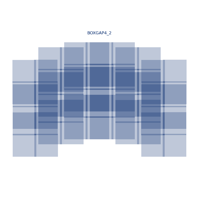
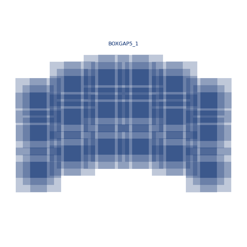
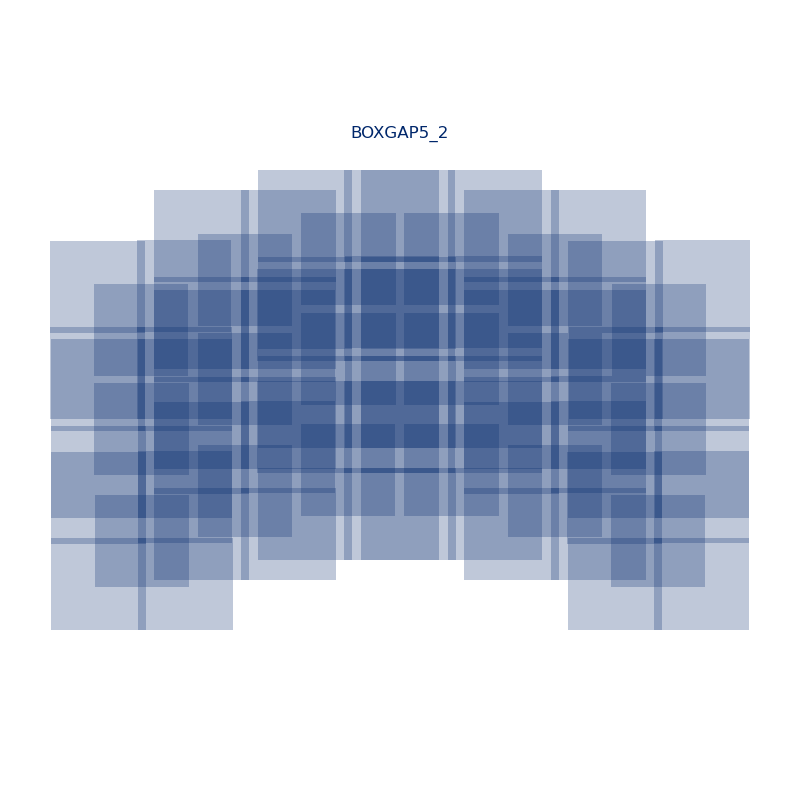
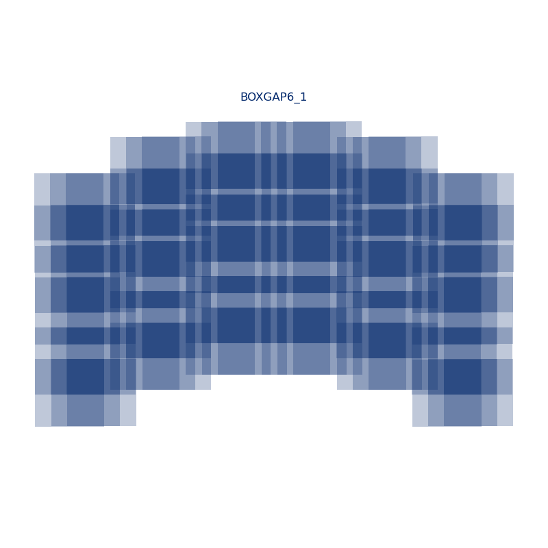
Gap-filling dither patterns (GAP) are large-scale offsets that require telescope slews. These patterns are primarily designed to fill the gaps between the WFI detectors by using pointings that slightly overlap. In addition, GAP dithers can help mitigate the effects of bad pixels (e.g., hot or dead pixels, or pixels affected by cosmic-ray hits) and reduce both inter-detector and intra-detector systematics.
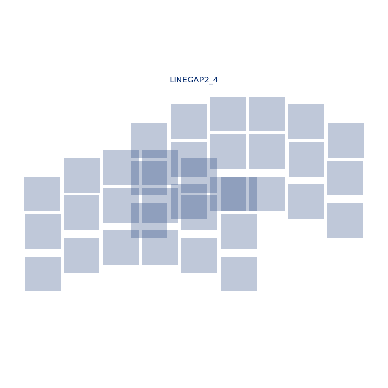
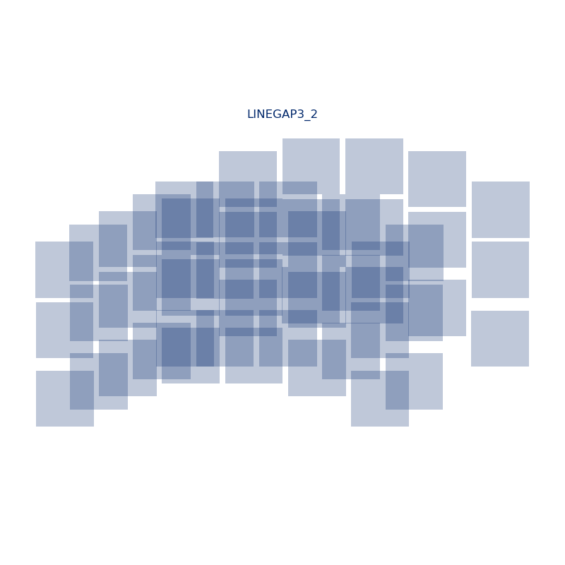
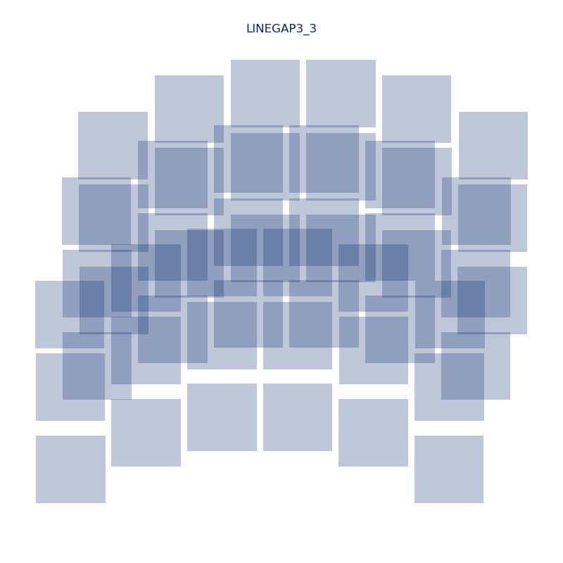
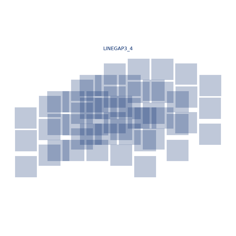
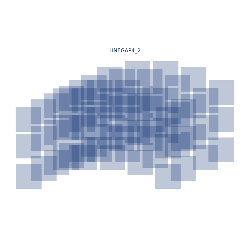
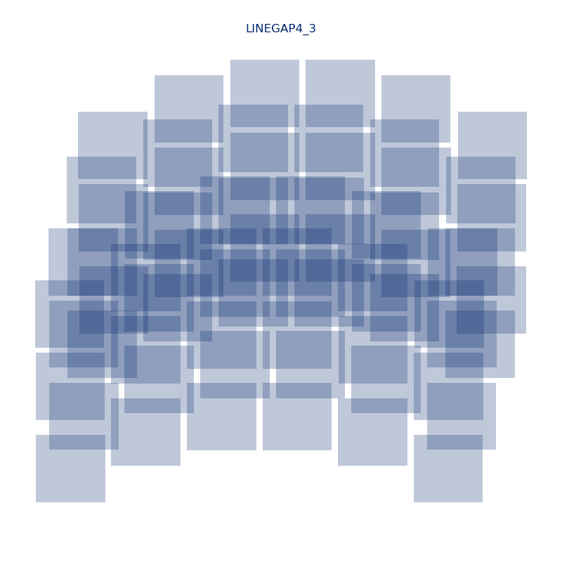
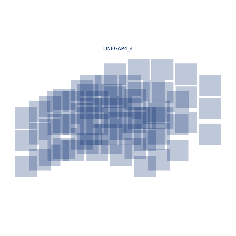
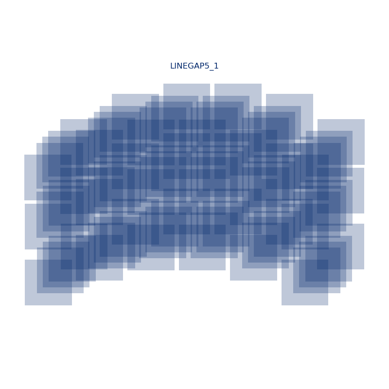
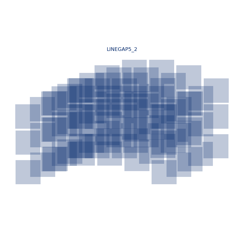
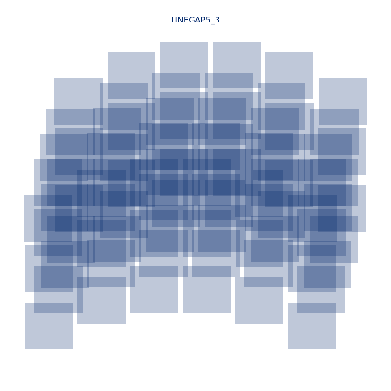
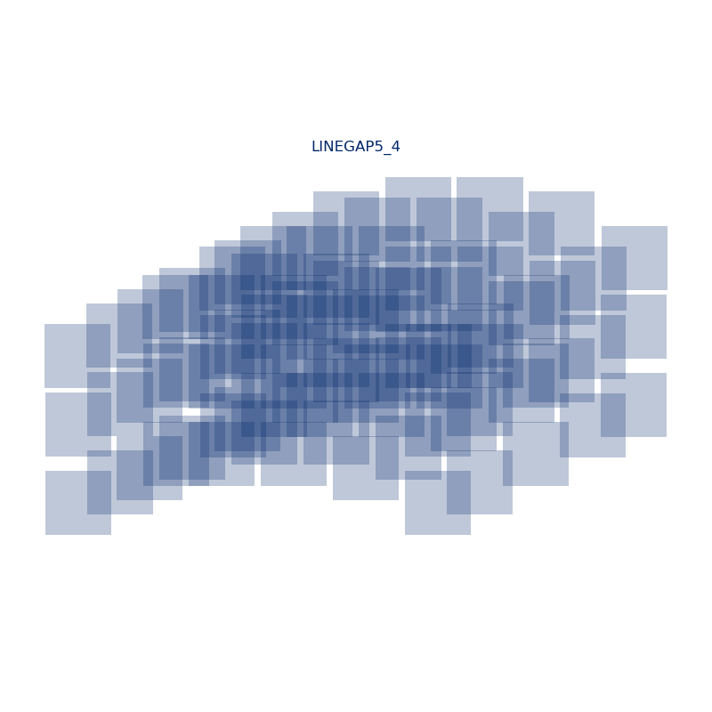
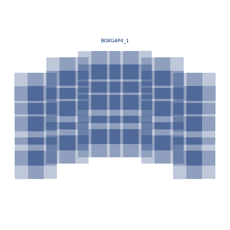
A GAP dither pattern is characterized by two main features: the geometric arrangement of the dither pointings and the number of pointings. Both of these properties are encoded in the name of the dither pattern. Currently, two geometries are supported: LINEGAP, in which pointings are arranged along a line, and BOXGAP, in which pointings are arranged in a grid.
Technical Note on Offsets and Sampling: While GAP patterns are large-scale, certain configurations (such as BOXGAP4) include small 0.88" offsets within their definition. At the WFI plate scale of 0.11"/pix, these 0.88" offsets correspond to integer pixel shifts (~8 pixels).
It is important to note that while these offsets provide "incidental" sub-pixel diversity, they are not designed to provide the controlled, uniform sub-pixel sampling required for high-precision PSF reconstruction. These offsets are calculated from a reference point and are not constant across the WFI FOV. A txt file of the constants can be found in the Data Tables and Downloads section at the bottom of this article. For optimal PSF sampling, users should select a SUB dither pattern in addition to their GAP pattern.
The gap-filling dither patterns currently available are summarized in the Table of Gap-Filling Dither Patterns. For additional details on GAP dither patterns and their use, see the Gap-filling dithers article.
Table of Gap-Filling Dither Patterns
Pattern Name | Number of Points | Type | Figure |
|---|---|---|---|
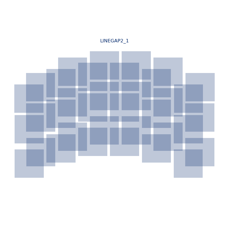
2 | line |
| |
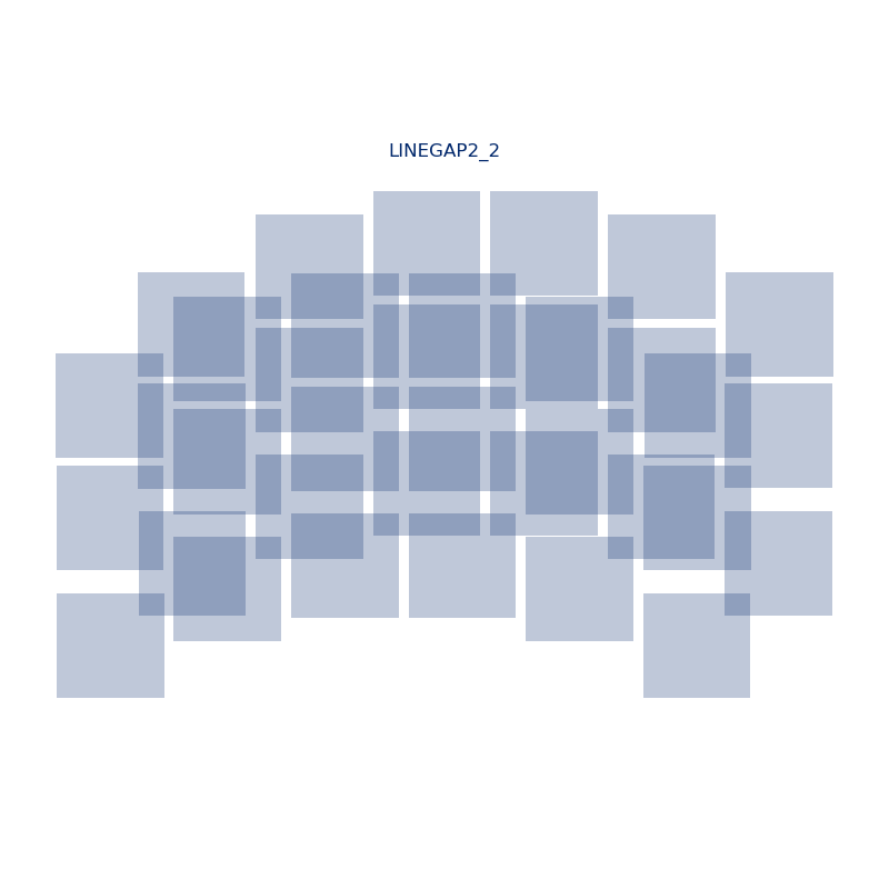
2 | line |
| |
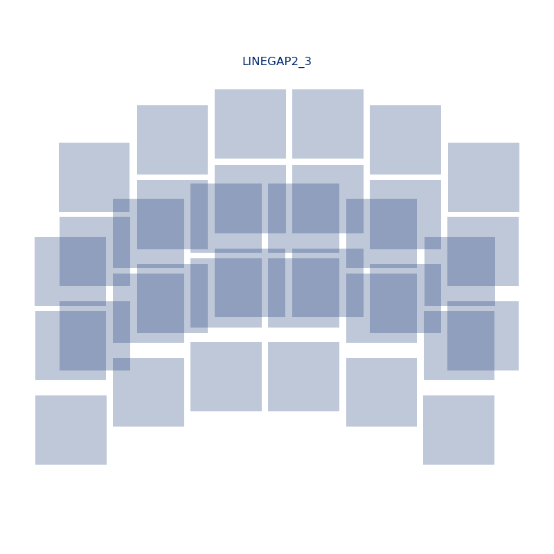
2 | line |
| |
2 | line |
| |
3 | line |
| |
3 | line |
| |
3 | line |
| |
3 | line |
| |
4 | line |
| |
4 | line |
| |
4 | line |
| |
4 | line |
| |
5 | line |
| |
5 | line |
| |
5 | line |
| |
5 | line |
| |
4 | box |
| |
4 | box |
| |
5 | box |
| |
| 5 | box |
| |
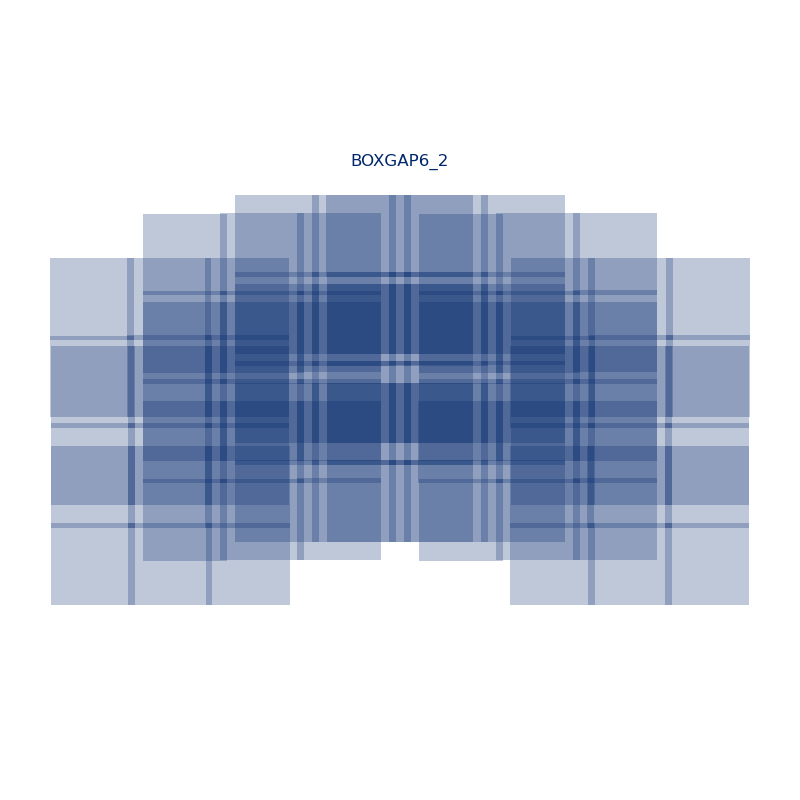
| 6 | box |
| |
| 6 | box |
| |
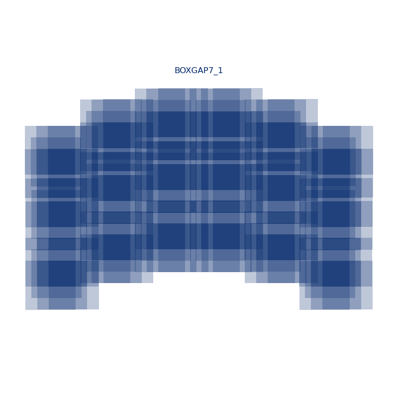
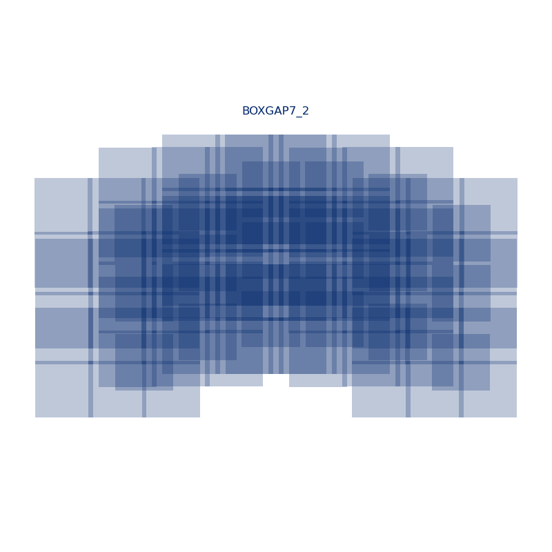
| 7 | box |
| |
| 7 | box |
| |
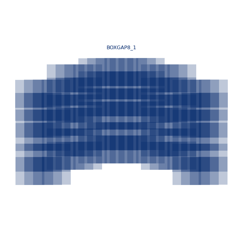
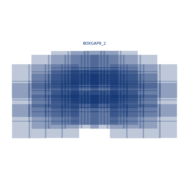
| 8 | box |
| |
| 8 | box |
| |
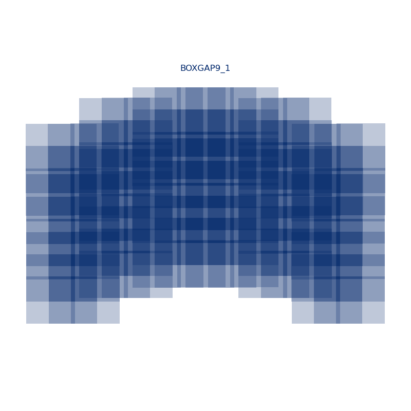
| 9 | box |
| |
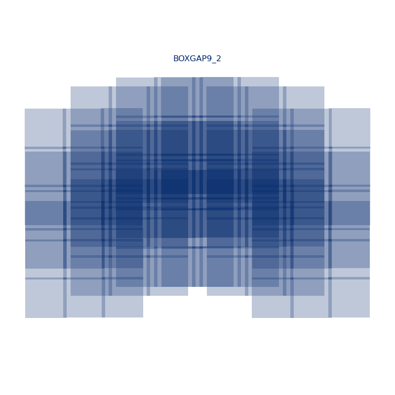
| 9 | box |
|


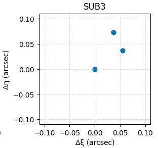
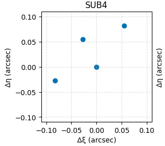
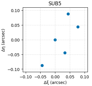
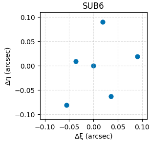
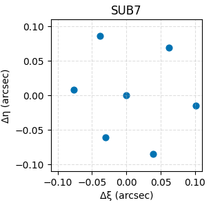
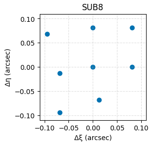
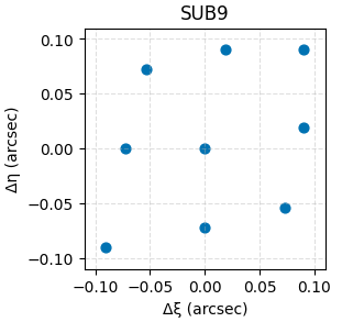
Sub-pixel Dither Patterns (SUB)
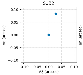
Sub-pixel dither patterns (SUB) are small-scale offsets designed to improve sub-pixel sampling and point-spread function (PSF) reconstruction. These patterns shift exposures by fractional pixel amounts without requiring large telescope slews, enabling efficient mitigation of intra-pixel sensitivity variations and improved sampling of the PSF.
The current set of SUB dither patterns includes eight options, SUB2 through SUB9, where the number after "SUB" indicates the total number of dither positions. Optimal sub-pixel sampling typically requires at least four positions; however, two- and three-point patterns can still provide partial improvements, particularly when used in combination with a larger GAP dither pattern.
The sub-pixel dither patterns currently available are listed in the Table of Sub-pixel Dither Patterns. For additional details on SUB dither patterns and their effective use, see the Sub-pixel Dithers article.
Data Tables and Downloads
The following ASCII files contain the relative shifts (offsets) for each WFI dither pattern.
Units: Arcseconds
Coordinate System: WFI Ideal Coordinate System
- Convention: Target offset
Gap-filling Dithers Data Tables
Subpixel dithers
For additional questions not answered in this article, please contact the Roman Help Desk.