PySIAF for Roman

This article contains information related to the use of PySIAF to perform coordinate transformations between the Wide Field Instrument (WFI) detector, the Roman spacecraft, and the sky.
Software Freeze: To ensure a stable user experience, updates to certain Roman tools will be suspended from June 28, 2026 through commissioning. Exceptions may be made for urgent fixes. Users will be notified of any releases made during this period.
The Science Instrument Aperture File (SIAF)
At a high level, the SIAF contains information related to the location of the WFI detectors relative to one another, and their absolute location in a spacecraft-based coordinate system. Combining this information with a model of the geometric distortion allows for the transformation between detector-based coordinate systems, the spacecraft coordinate system, and the sky (when a spacecraft attitude matrix is also supplied). Supported coordinate systems are listed below, and more information is available in the Coordinate Systems article.
Table of SIAF Coordinate Systems
| System Name | Abbreviation | Definition |
|---|---|---|
| Detector | det | The detector coordinate system is defined by the fast and slow readout electronics on each Sensor Chip Assembly (SCA). The corner of the SCA where these readouts meet is defined as the origin of the system, with the x-axis increasing along the fast scanner away from the slow scanner, while the y-axis increases along the slow scanner away from the fast scanner. The electronics-based location of the detector frame origin means that WFI03, 06, 09, 12, 15, and 18 have a different orientation in this coordinate system than the other SCAs (see the Figure of Coordinate Systems for WFI). |
| Science | sci | The science coordinate system is defined such that the origin is always located at the bottom-left corner of the SCA when the focal plane is viewed in an orientation with WFI16 located in the upper-left and WFI07 located in the upper-right (see the Figure of Coordinate Systems for WFI). The science coordinate frame is measured in pixels, and only includes the sky-exposed 4088 x 4088 pixel array (i.e., not the 4-pixel border of reference pixels). For example:
|
| Ideal | idl | The ideal coordinate system accounts for the effects of geometric distortion. The center of the coordinate system is the center of the SCA, with the y-axis of the ideal coordinate system parallel to the y-axis of the science coordinate system by definition. The ideal x-axis increases in the same direction as the science x-axis, but due to distortion may not be perfectly parallel to it. The ideal coordinate system is measured in arcseconds. |
| Telescope (V-frame) | tel | The telescope (also called V-frame) coordinate system is defined such that the boresight of the telescope is located at the origin. There are three axes, though in principle only two are used in the SIAF:
The telescope coordinate system is measured in arcseconds. Note that due to the right-handed nature of the coordinate system, the V2-axis increases to the left when viewed in projection. |
| Sky | sky | The sky coordinate system is a system of right ascension and declination on the sphere of the sky. To compute a transformation to the sky, attitude information for the spacecraft must be supplied including the right ascension and declination at the telescope boresight as well as the position angle of the V3 axis. |
A copy of the Roman SIAF is included as supplemental data in the PySIAF package installation.
The SIAF contains a list of "apertures," with each aperture having information related to reference positions and distortion coefficients. Some apertures are collections of others to be used for pointing, e.g., the main WFI aperture is called "WFI_CEN". For the purpose of transforming coordinates from pixels to angular positions, a geometric distortion model is required, and is defined as a tangent plane projection at the center of each WFI SCA. For this reason, each SCA is also stored as an aperture, e.g., "WFI01_FULL". It is crucial to utilize these SCA apertures for accurate mapping between pixel coordinates and corresponding angular position. "WFI_CEN" should instead be used to obtain the overall pointing of the WFI on the sky. This is illustrated in the Figure of Coordinate Systems for WFI and in the Figure of WFI and Coronagraph Apertures, which can be produced using the examples below.
Figure of Coordinate Systems for WFI
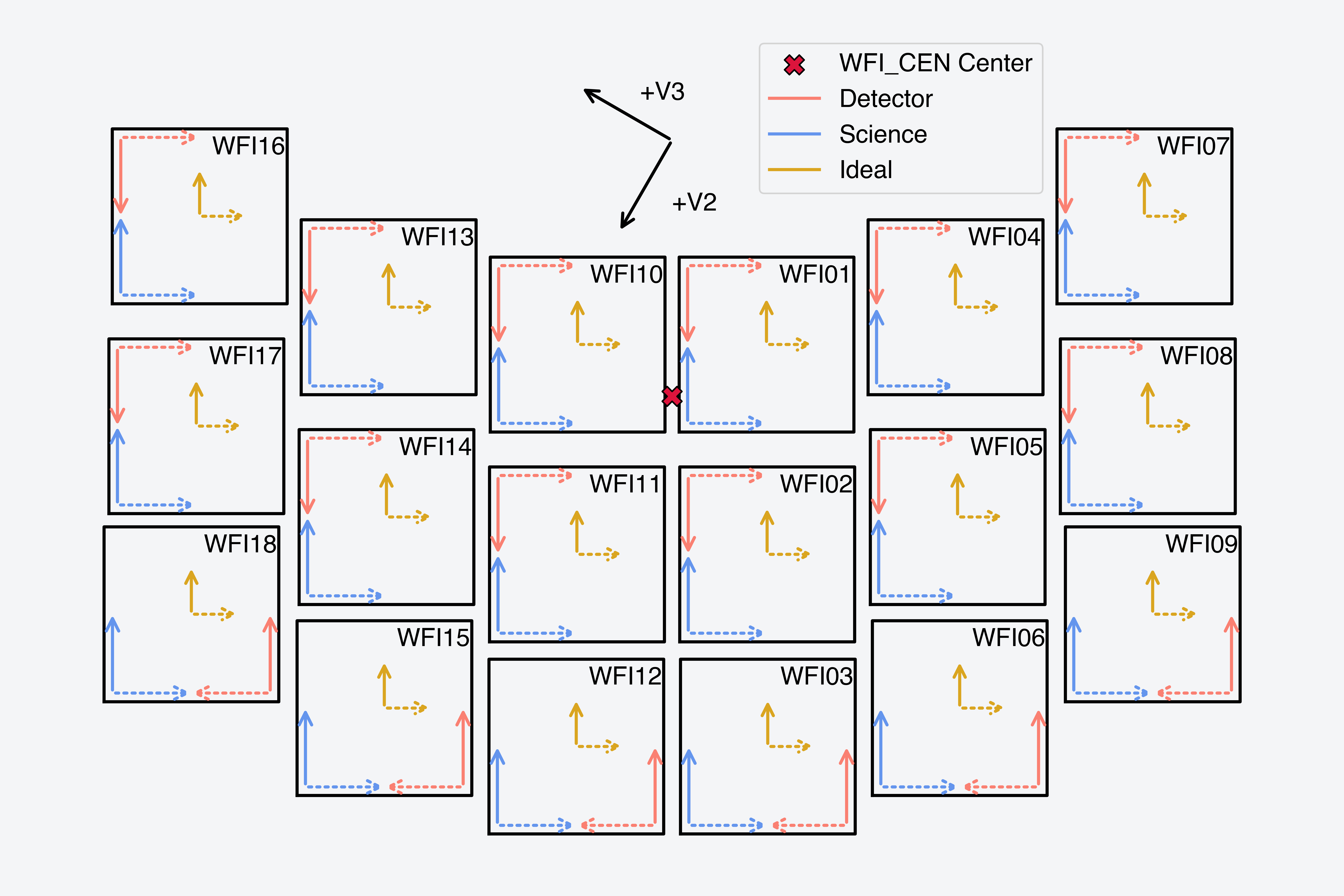
Definition of the SIAF coordinate systems including the detector, science, and ideal coordinate frames. The telescope (V-frame) axis orientation is shown for reference. The x-axis of each coordinate system is shown as a dashed line, while the y-axis of each system is shown as a solid line.
PySIAF
The PySIAF Python package (Sahlmann et al. 2019) contains functions, classes, and methods necessary for reading the Roman SIAF XML (extensible markup language) file. Using information from the SIAF, PySIAF computes transformations between the various coordinate systems used in the planning and analysis of WFI observations (see Table of SIAF Coordinate Systems).
Code Repository and Documentation
The PySIAF code is publicly developed and available on GitHub, and the application programming interface (API) documentation is available on readthedocs. Users are encouraged to open issues on the repository to provide feedback or report problems.
Installation
The
PySIAF
code is installable via pip.
Users are advised to always use the latest released version of PySIAF to ensure that both the correct reference information is used and the correct dependency versions are installed in the environment.
Basic installation of PySIAF on a Unix-like operating system using a Conda environment manager can be accomplished in a shell by typing the following:
$ conda create -n <environment_name> python
$ conda activate <environment_name>
$ pip install pysiaf
Note that the $ symbol indicates the shell prompt. The variable <environment_name> is at the discretion of the user. By indicating the argument "python" during the environment creation, the latest available version of Python will be installed in the environment along with other necessary tools such as pip.
Use Cases and Examples
Read the Roman SIAF into a Python Class
PySIAF can read the Roman SIAF XML file into a Python class that can be used to select various apertures and use their reference information. To read in the Roman SIAF, in Python type the following:
# Imports
import matplotlib.pyplot as plt
import pysiaf
from pysiaf.utils.rotations import attitude

# Read in the Roman SIAF
rsiaf = pysiaf.Siaf('Roman')

# Print information about the WFI01_FULL aperture
wfi01 = rsiaf['WFI01_FULL']
print(f'WFI01 Xsci Ref: {wfi01.XSciRef}')
print(f'WFI01 Ysci Ref: {wfi01.YSciRef}')
print(f'WFI01 V2 Ref: {wfi01.V2Ref}')
print(f'WFI01 V3 Ref: {wfi01.V3Ref}')
Running the above should yield something similar to the following:
WFI01 Xsci Ref: 2044.5
WFI01 Ysci Ref: 2044.5
WFI01 V2 Ref: 1312.9491452484797
WFI01 V3 Ref: -1040.7853726755036
To plot all of the detectors, both WFI and the Coronagraph Instrument on the telescope ("V") frame, type:
# Plot the Roman apertures on the telescope ("V") frame
roman_apertures = [f'WFI{i + 1:02}_FULL' for i in range(18)]
roman_apertures.append('CGI_CEN')

fig, ax = plt.subplots()

for rap in roman_apertures:
    color = 'salmon' if 'WFI' in rap else 'cyan'
    rsiaf[rap].plot(color=color)

# Add guide lines for boresight (V2, V3) = (0, 0)
ylim = ax.get_ylim()
xlim = ax.get_xlim()
ax.plot([0, 0], ylim, color='black', linestyle=':', alpha=0.3)
ax.plot(xlim, [0, 0], color='black', linestyle=':', alpha=0.3)

# Set the axis limits and invert the X-axis such that V2 is
# positive to the left
ax.set_xlim(xlim)
ax.set_ylim(ylim)
ax.invert_xaxis()

# Save figure
plt.savefig('pysiaf_roman_apertures.png')
The code snippets above should produce a figure similar to the following:
Figure of WFI and Coronagraph Apertures
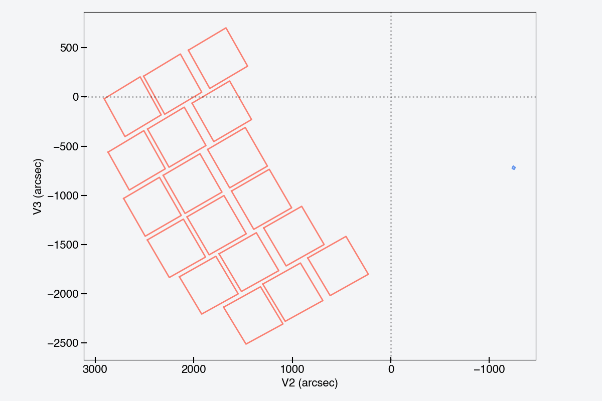
The WFI and Coronagraph apertures in the telescope focal plane. The apertures are plotted on the telescope ("V") frame with the WFI detectors shown in salmon red, while the Coronagraph Instrument is displayed in cornflower blue.
Transformation Between Systems
A user may need to translate between various coordinate systems, such as the science and detector systems. Transformations between relative coordinates (i.e., all systems that are not on-sky) may include simple shifts, geometric-distortion-correction transformations, and rotations on a sphere. These transformations are all simplified by the methods on the aperture objects in PySIAF .
To transform from WFI01 science (x, y) = (1, 1) to the detector, ideal, and telescope frames, in Python type the following:
det_xy = wfi01.sci_to_det(1, 1)
idl_xy = wfi01.sci_to_idl(1, 1)
tel_xy = wfi01.sci_to_tel(1, 1)

print('WFI01 Science (x, y) = (1, 1)')
print(f'WFI Detector (x, y) = ({det_xy[0]:.1f}, {det_xy[1]:.1f}) pixels')
print(f'WFI Ideal (x, y) = ({idl_xy[0]:.5f}, {idl_xy[1]:.5f}) arcseconds')
print(f'WFI Telescope (x, y) = ({tel_xy[0]:.5f}, {tel_xy[1]:.5f}) arcseconds')
This should yield something similar to the following:
WFI01 Science (x, y) = (1, 1)
WFI Detector (x, y) = (5.0, 4092.0) pixels
WFI Ideal (x, y) = (-225.69567, -220.75499) arcseconds
WFI Telescope (x, y) = (1616.97641, -955.70469) arcseconds
Note that in these examples we have used Python f-string format codes to limit the number of decimal places displayed.
Pixels on the WFI in the science and detector coordinate systems are 1-indexed. The center of the first pixel adjacent to the origin in the respective systems has coordinates (x, y) = (1, 1). Note that the definition of the origin is different for the science and detector coordinate frames.
To transform to the sky, one must also supply an attitude matrix, which can be generated with PySIAF . This attitude matrix is constructed from the on-sky position of the V1 axis, i.e., the boresight, in right ascension and declination, as well as the position angle of the V3 axis measured at the boresight and counterclockwise from North.
Here we show how to determine the right ascension and declination of the reference position for the WFI_CEN aperture, which represents the geometric center of the WFI focal plane array, and is the default target position for observations with the WFI:
# Set the boresight position and roll angle
boresight_ra = 93.485
boresight_dec = -10.22385
pa_v3 = 172.935

att = attitude(0, 0, boresight_ra, boresight_dec, pa_v3)

# Compute the sky coordinates of the WFI_CEN aperture reference position
wfi_cen = rsiaf['WFI_CEN']
wfi_cen.set_attitude_matrix(att)
wfi_ra, wfi_dec = wfi_cen.idl_to_sky(0, 0)
print(f'WFI_CEN RA = {wfi_ra:.5f} deg, Dec = {wfi_dec:.5f} deg')
This should yield values like:
WFI_CEN RA = 93.02112 deg, Dec = -10.03024 deg
This can be applied to any position on the WFI. For example, we could apply the same attitude matrix, and determine a grid of pixel positions on one of the SCAs in sky coordinates. Here is an example using the science (x, y) = (1, 1) pixels coordinate on WFI18 and the same attitude matrix:
wfi18 = rsiaf['WFI18_FULL']
wfi18.set_attitude_matrix(att)
wfi18_ra, wfi18_dec = wfi18.sci_to_sky(1, 1)
print(f'WFI18 (Xsci, Ysci) = (1, 1) pixels, (RA, Dec) = ({wfi18_ra:.8f}, {wfi18_dec:.8f}) deg')
Yields:
WFI18 (Xsci, Ysci) = (1, 1) pixels, (RA, Dec) = (92.66926077, -10.31726044) deg
The inverse operation may also be performed, i.e., transforming from a sky position to coordinates on the detectors. This is helpful for determining where a source may be located given some input pointing parameters. Here we set up a new attitude matrix supposing that we know where we intend for the center of the WFI to be placed on the sky, and we determine the science pixel positions of a given sky coordinate:
# Set the WFI center to be placed at RA, Dec = (80.0, 30.0) with the position
# angle of the V3 axis set to 0.
att = attitude(wfi_cen.V2Ref, wfi_cen.V3Ref, 80.0, 30.0, 0)
wfi01.set_attitude_matrix(att)
x, y = wfi01.sky_to_sci(79.91629, 30.00603)
print(f'WFI01 (RA, Dec) = (79.91629, 30.00603), (Xsci, Ysci) = ({x:.3f}, {y:.3f})')
Yields:
WFI01 (RA, Dec) = (79.91629, 30.00603), (Xsci, Ysci) = (835.452, 3049.258)
Care must be taken to use the correct SCA when computing the transformation between sky and pixel positions. If not properly selected, the incorrect geometric distortion model may be used, which may shift sky positions many pixels away from their correct location. Other tools, such as geopandas , may be used to determine bounding boxes for the SCAs within which sky positions are located.
References
- PySIAF, Readthedocs maintained by STScI 2023
- Sahlmann, J., Osborne, S., Cox, C., Proffitt, C. R., Law, D., Perrin, M., Boyer, M., & Hunkeler, J. 2019, https://zenodo.org/record/3516964
- Cox, C. & Lallo, M. 2017, "Description and Use of the JWST Science Instrument Aperture File", JWST-STScI-001550
For additional questions not answered in this article, please contact the Roman Help Desk.