Appendix: WFI Dithering
The WFI observation configurations permits a set number of Dither Patterns. There are two types of dither patterns: (1) those that fill detector gaps, GAP Dither Patterns, and (2) those that provide sub-pixel sampling, SUB Dither Patterns. The options for both are described below.
Dither Pattern Overview
WFI dither patterns can be selected in APT (see Pass Plans), and used in concert, to accomplish multiple goals: fill gaps in sky coverage between the 18 detectors, mitigate flat field uncertainties and scattered light, and provide sub-pixel sampling. Dithers are executed in the coordinate system of the WFI aperture selected. Small-grid dithers can be executed very efficiently with fine steering, whereas larger dithers require telescope slews and additional overhead time. The maximum distance allowed between pointings in a single visit is a function of Galactic latitude for Fixed Targets. Dither Patterns are executed for each Tile within the user-defined Mosaic Patterns to define the overall pointing strategy within a Segment. GAP Dither Patterns and SUB dither patterns can be used at the same time and the SUB dither will be executed for each pointing in the GAP Dither.
Changes to the technical details and other specifications presented here are expected as a part of the process of defining the Core Community Surveys.
Gap-filling dither patterns (GAP)
GAP dither patterns are large-scale shifts that require telescope slews. These patterns are designed to fill-in the gaps between the WFI detectors, with overlaps that are small compared to the field-of-view. The strategy behind each GAP pattern is provided in the Table Describing GAP Dither Patterns and in the Figure of Gap Filling Dither Patterns. Most GAP patterns perform the minimal shift needed to span the gaps between the detectors (with small overlaps), but the WIDE versions perform the maximum shift that covers the gaps, as a tradeoff between expanding the field of view and exposure depth.
Table Describing GAP Dither Patterns
| GAP Dither Pattern | number of pointings | Description |
|---|---|---|
| NONE | 1 | default, one pointing (no dithering) |
| LINEGAP2 | 2 | minimal and incomplete gap coverage |
| LINEGAP3 | 3 | minimal and incomplete gap coverage |
| LINEGAP4 | 4 | minimal and complete gap coverage in a line |
| BOXGAP4 | 4 | minimal and complete gap coverage in two dimensions |
| WIDEGAP4 | 4 | minimal and complete gap coverage with tradeoff between larger field-of-view and thinner exposure depth |
| BOXGAP5 | 5 | LINEGAP3 plus LINEGAP2 offset by 200 arsec in x |
| BOXGAP6 | 6 | Two LINEGAP3 patterns offset by 25 arcsec in x |
| WIDEGAP6 | 6 | Three LINEGAP2 patterns offset by 425 arcsec |
| BOXGAP7 | 7 | BOXGAP6 plus an extra step for slightly more uniform exposure depth |
| BOXGAP8 | 8 | Two BOXGAP4 patterns with 425 arcsec offset |
| BOXGAP9 | 9 | BOXGAP4 with a third step in both dimensions |
| WIDEGAP9 | 9 | WIDEGAP4 with a third step in both dimensions |
Changes to the technical details and other specifications presented here are expected as a part of the process of defining the Core Community Surveys. This includes modifications to the Dither patterns.
Figure of Gap-filling Dither Patterns

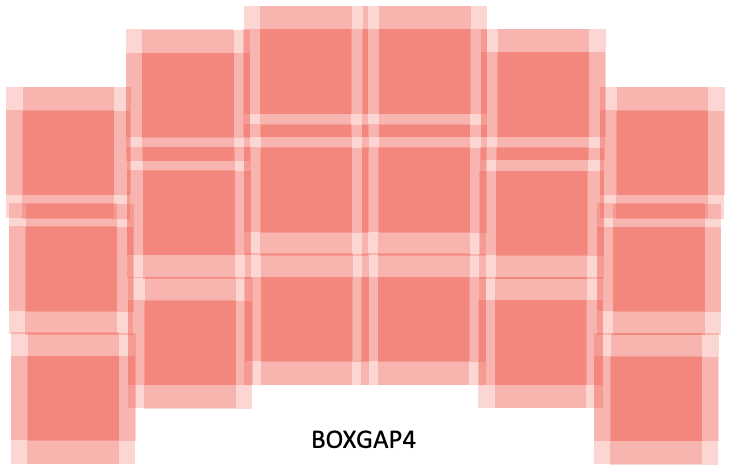

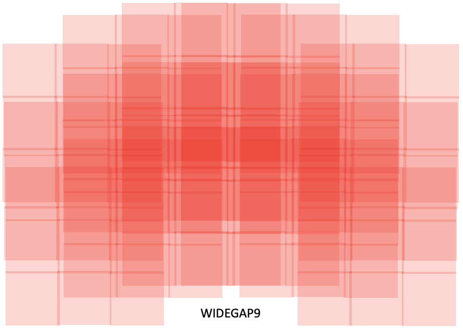
Illustrations of four GAP dither patterns – LINEGAP3, BOXGAP4, WIDEGAP4, and WIDEGAP9 (as projected on the sky), indicating the varying exposure depth across the field-of-view. Darker color indicates greater total exposure time. Note that the LINEGAP3 pattern does not provide complete gap-filling. The WIDEGAP4 pattern covers a larger area than BOXGAP4 at the expense of exposure depth and uniformity.
Changes to the technical details and other specifications presented here are expected as a part of the process of defining the Core Community Surveys. This includes modifications to the Dither patterns.
Subpixel dither patterns (SUB)
SUB dither patterns are small-scale shifts designed for subpixel sampling. The initial set includes only small-grid subpixel patterns which can be executed very efficiently, as they do not require telescope slews. Standard (larger) subpixel dithers, and dithers optimized for slitless spectroscopy, will be added as needed. Optimal subsampling requires at least 4 dither points, but some benefit is derived from the 2 and 3 point dithers (especially in concert with a GAP dither). The options are: NONE (default), SUB2, SUB3, SUB4, SUB5, SUB6, SUB7, SUB8, SUB9 where the number after "SUB" indicates the number of sub-pixel dithers.
The positions for the eight SUB dither patterns are shown in the Figure of Sub-pixel Dither Patterns.
Figure of Subpixel Dither Patterns
![]()
Plots of the Roman WFI small-grid subpixel (SUB) dither patterns, as projected on the detector. These are the JWST NIRCam small-grid subpixel patterns modified for the WFI plate scale (0.11 arcsec per pixel).
Changes to the technical details and other specifications presented here are expected as a part of the process of defining the Core Community Surveys. This includes modifications to the Dither patterns.