Calibration
Calibration data are taken obtained using Special Requirements. The use of the
CALIBRATION
Special Requirement is described below.
Calibration Special Requirement
CALIBRATION CALIBRATION TYPE LAMP STATE
The CALIBRATION special requirement is motivated by the need to enable certain modes of observation that are considered only desirable for calibration observations. Some such modes activate internal lamps or block outside light, and as such can be detrimental to general astrophysical observations. As a consequence, the CALIBRATION special requirement is only available when Allow Restricted is selected (see Program Information).
The CALIBRATION special requirement is applied individually to selected observation specifications within a Pass Plan.
This requirement specifies that the selected observation specification is used for calibration, using the specified CALIBRATION TYPE and LAMP STATE . The CALIBRATION TYPE chosen determines whether the DARK element is selected in the Element Wheel, thus blocking external light, and whether the internal light source is turned on with the appropriate specifications indicated in LAMP STATE . Details are given in Table 1 below.
CALIBRATION and ENGINEERING special requirements are not allowed on the same observation.
<CALIBRATION TYPE>
Calibration types are: Dark Imaging, Dark Spectroscopy, Internal Flat, CRNL Direct Illumination, CRNL LOLO. CALIBRATION TYPE is required.
Depending on the CALIBRATION TYPE , certain parameters of the observation specification are set to required values and cannot be changed (see Table 1).
Calibration Types Dark Imaging and Dark Spectroscopy are used to obtain dark images to generate dark calibration reference frames. These images will be taken with the DARK element in the Element Wheel and with lamps turned on. No dither shall be specified, although a repeat count is allowed. These observations will typically use the diagnostic MultiAccum table and use guide windows of sizes appropriate to Imaging (16x16) and Spectroscopy (32x16), respectively. The position of the guide window needs to be randomized.
Calibration types Internal Flat and CRNL Direct Illumination are used to obtain frames illuminated by the internal light sources. The DARK element of the Element Wheel is in place. LAMP STATE specifies how many exposures are taken and at which lamp wavelength and illumination level. Typically, Internal Flats will be obtained with a bright lamp setting suitable to collect about 50k electrons per pixel in a 50s exposure. CRNL Direct Illumination data will be obtained with a combination of two lamps at the same wavelength, turned on at different settings; a sequence of several dozen such combinations will be taken in order to calibrate the nonlinearity of the detector using the Combinatorial Flux Addition method. More information under LAMP STATE .
Calibration Type CRNL LOLO is used to obtain an image of the sky superimposed with light from the internal source. Pointing, OPTICAL ELEMENT , and DITHER are defined as with any other exposure. A lamp associated with the selected optical element needs to be turned on at the desired intensity; lamp light is back-reflected by the cold mask on the filter and added to the scene light. Note that there is no lamp associated with the optical element F213.
Table 1. Required Observation Specification parameters by CALIBRATION TYPE
CALIBRATION TYPE | TARGET | OPTICAL ELEMENT | MOSAIC | DITHER | SUBPIXEL DITHER | EXPOSURES/DITHER |
|---|---|---|---|---|---|---|
| Dark Imaging | NONE | DARK | NONE | NONE | NONE | |
| Dark Spectroscopy | NONE | DARK | NONE | NONE | NONE | |
| Internal Flat | NONE | DARK | NONE | NONE | NONE | Equal to number of exposures in the lamp state |
| CRNL Direct Illumination | NONE | DARK | NONE | NONE | NONE | Equal to number of exposures in the lamp state |
| CRNL LOLO | (selected fixed target) | (selected optical element) | (selected mosaic) | (selected dither) | (selected subpixel dither) | Equal to number of exposures in the lamp state |
<LAMP STATE>
LAMP STATE specifies the state of active lamps for each exposure.
There are 12 LED lamps (2 pairs at each of 6 different wavelengths). Calibrations using the lamps may have sequences up to 100 exposures with different subsets of lamps selected for each exposure and different power levels configured for each lamp. Lamp power levels (lamp states) are discrete integers ranging from 1 to 128.
LAMP STATE
is available and required when
CALIBRATION TYPE
is Internal Flat, CRNL Direct Illumination, or CRNL LOLO. The use of the lamp is different for each of these cases.
For Internal Flat observations, one lamp is turned on for one of the six bands at a high flux level, suitable to collect 50K electrons per pixel per exposure. (A typical exposure may be around 50s.) Multiple exposures are obtained until at least 10^6 electrons per pixel are collected in that band. The process is then repeated for the other 5 bands. Two lamps for the same band can be turned on if needed to achieve the desired luminosity. The
DARK
element is in use throughout, and the light is diffused by the back of the
DARK
element.
For CRNL Direct Illumination observations, a sequence of observations is taken with both lamps in the same band turned on. During the sequence, the intensity setting of both lamps is cycled through several values, resulting in images with multiple levels of illumination. The Combinatorial Flux Addition method is then used to determine any deviation from linearity in the detector response (after correction for classic nonlinearity). This procedure can constrain non-linearity over a broad range of impinging fluxes and total count levels. The procedure is then repeated for other bands as needed. As for the Internal Flat observations, the lamp light is diffused by the back of the Dark element, which is in place throughout. Note that the exposure length may need to change depending on the lamp setting; at low intensity, long exposures are needed to collect enough counts, while at high intensity, short exposures are needed to avoid saturation. Using the number of elements in the sequence to determine number of exposures is only useful for sequences of exposures reaching similar level of total lamp flux.
For CRNL LOLO, the telescope is pointed at a carefully chosen external scene, with the desired filter, pointing, and dithering options. The CRNL LOLO observations are characterized by turning on one lamp corresponding to the optical element chosen; its light is diffused by the cold mask in the filter, and added to the signal received by the detector. This provides the essence of the Lamp-On/Lamp-Off (LOLO) process; the change in signal in a source when a smooth illumination (from the internal lamp) is added provides constraints on the detector linearity at that signal level. Typically we expect the observing sequence to be repeated with lamp off, lamp on at low setting, and lamp on at higher setting. Note that there is no lamp suitable for use with F213.
<LAMP STATE> entry format
The format of LAMP STATE is multiple lines, each starting with an exposure number followed by some number of lamp state directives. Each element, including the exposure number, must be separated by a comma.
A
LAMP STATE
directive is an 'L' followed by the lamp number, then an '=', then the lamp state as an integer in 1-128. Ex: L10 = 22.
Whitespace around the '=' is optional but should not be present in the exported SQL.
An example:
1, L10 = 33, L2 = 20
2, L3 = 40, L5 = 21
<LAMP STATE> Usage
Table 2. Lamp usage where EXPOSURE NUMBER , L LAMP NUMBER = LAMP STATE
Element | Lamp Usage |
|---|---|
EXPOSURE NUMBER | sequential number from 1-100 , must start with 1 |
LAMP NUMBER | lamp number from 1-12 |
LAMP STATE | lamp state number from 1-128 (power level) |
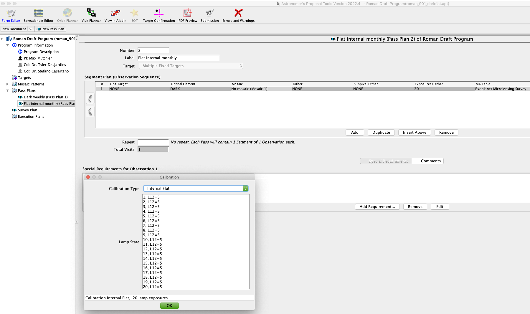
Figure 1: LAMP STATE entry in the Roman APT user interface. The entry above would generate 20 internal flat exposures with lamp 12 at power level 5.
For additional questions not answered in this article, please contact the Roman Help Desk at STScI.