Description of the WFI

The Wide Field Instrument (WFI) is critical to Roman's survey capabilities. This article presents a high-level overview of the WFI, followed by a more detailed introduction to two of its major subsystems: the Focal Plane Array (FPA) and the Relative Calibration System (RCS).
Introduction
The Wide Field Instrument (WFI) of the Roman Space Telescope has both imaging and slitless spectroscopy capabilities, and a large field of view. The active area on the sky is 0.281 square degrees, roughly 100 times the area covered by HST/ACS or JWST/NIRCam, and 200 times that of WFC3/IR. The WFI has 18 H4RG-10 (HgCdTe) 4096 pixel by 4096 pixel detectors for over 300 million active pixels with a plate scale of 0.11 arcseconds. The WFI is sensitive to wavelengths from 0.48 to 2.3 microns. The Element Wheel Assembly has eleven spots, ten of which are used for optical elements and one is a DARK element used for calibration purposes. The optical elements comprise seven standard filters, spaced by about 40% in central wavelength, an ultrawide filter, a medium-resolution grism (R ~ 460 - 890), and a low-resolution prism (R ~ 80-180). At-a-glance information on the filters are given in the WFI Quick Reference article and detailed descriptions of the optical elements are given in the WFI Optical Elements article.
The Figure of the WFI on the Spacecraft shows where the WFI fits into the spacecraft design. The inlay shows a photograph of the WFI after it was fully assembled in September 2023, helping to illustrate how the instrument fits into the telescope. The Schematic of the WFI and its Subsystems presents a cross-sectional view: on the left, it shows how light enters the instrument, and on the right, it highlights the locations of key subsystems. Light enters through the cold baffle reaching the Focal Plane Array, which is operated through the Sensor Control Electronics Assembly. The Focal Plane Electronics are located towards the outer part of the instrument. An internal calibration system, the Relative Calibration System (RCS) can illuminate the detectors. All of the optics are on an Optical Bench that can be finely adjusted with the Alignment Compensation Mechanism (ACM). The instrument has three distinct thermal zones that are all passively cooled. The Mosaic Plate Assembly (on which the 18 detectors are mounted) is the coolest, operating around ~90 K (or cooler), the Sensor Control Electronics Assembly is at about 140 K, and the Focal Plane Electronics at about 190 K; three radiators help maintain the desired operating temperature for each zone of the WFI.
Figure of the WFI on the Spacecraft
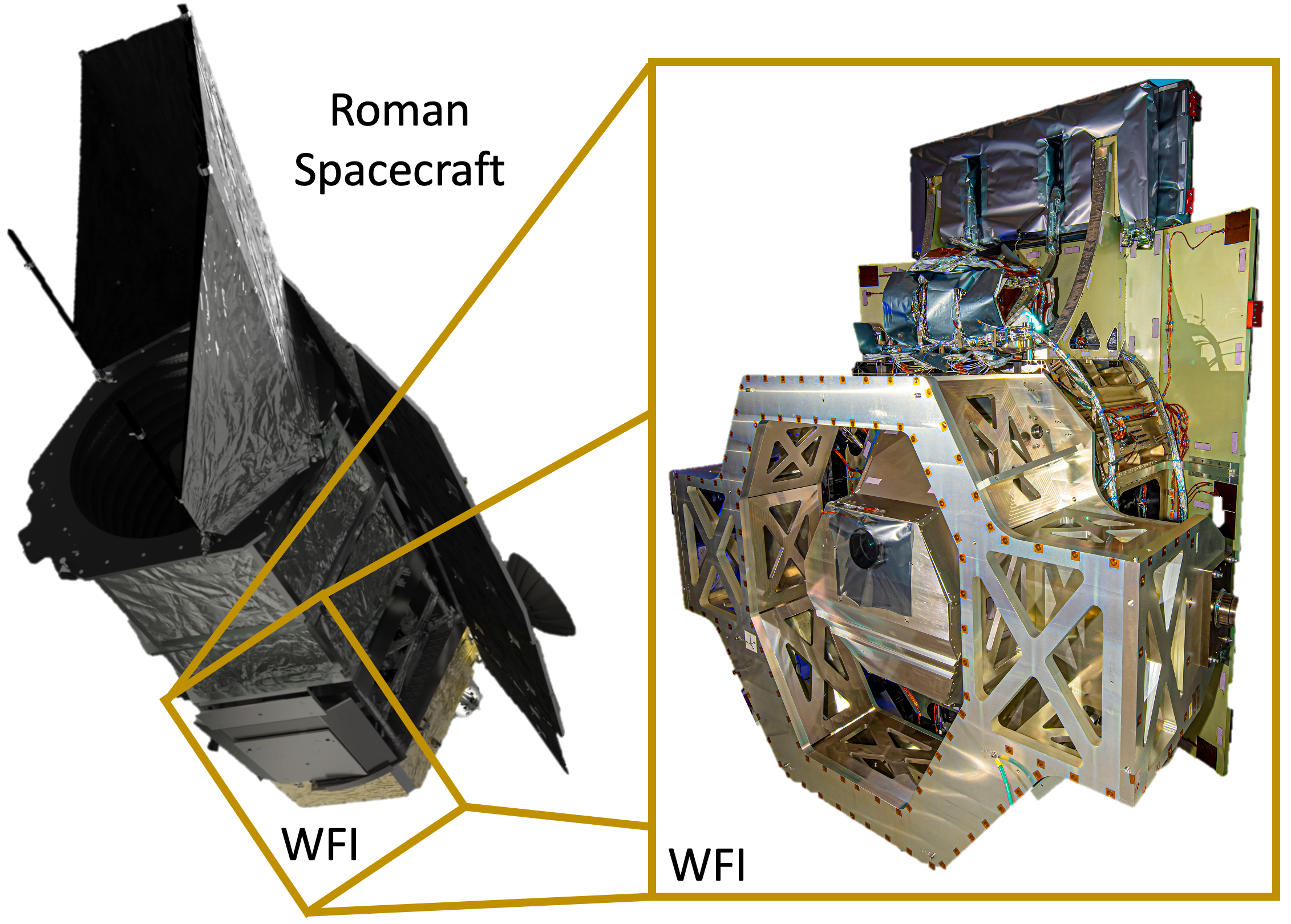
On the left is a visualization of the Roman spacecraft in its final design (Image Credit: NASA's Goddard Space Flight Center; Link to Original). A dark-yellow box highlights the outer panel of the WFI once it is installed in the observatory. The dark-yellow box connects out to a view of the WFI on the right that was taken after integration of its subsystems for the instrument-testing campaign at BAE Systems (formerly Ball Aerospace) but before it was wrapped in its thermal insulation. Much of the instrument is visible (Image Credit: Ball Aerospace; Link to Original). The panel that shows on the outside of the telescope on the left is on the back of the instrument in this view.
Schematic of the WFI and its Subsystems
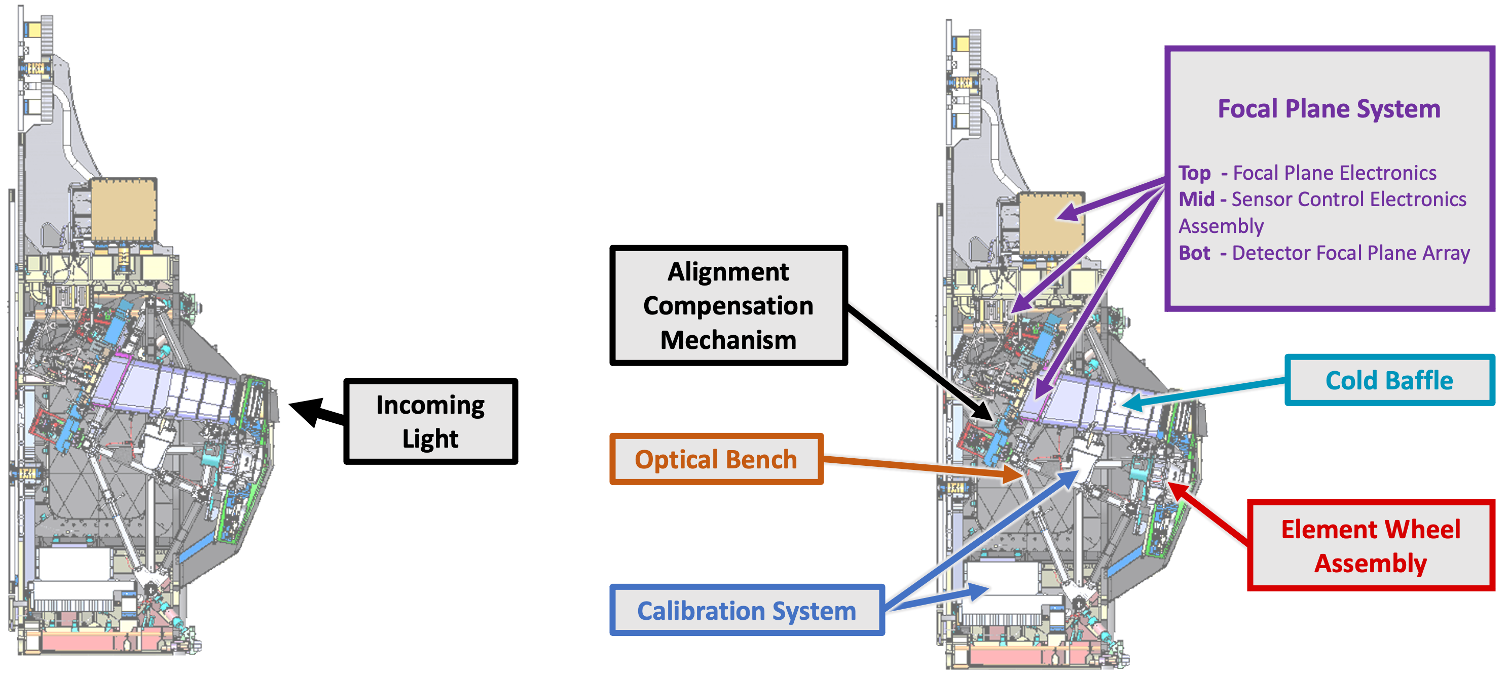
In these schematics, the WFI is viewed edge-on such that the left panel shows the light incoming from the telescope, which faces in toward the telescope in the Figure of the WFI on the Spacecraft above. The panel on the right is the same view of the WFI with some of its major sub-systems identified. Going counterclockwise from the top, the WFI sub-systems identified are the Alignment Compensation Mechanism (ACM), the Optical Bench, the two parts of the Calibration System (the RCS and its control electronics), the Element Wheel Assembly that houses the optical elements, the Cold Baffle, and the Focal Plane System (the location of the Focal Plane Array (FPA) that houses the detectors, the Sensor Control Electronics Assembly (SCEA), and the Focal Plane Electronics (FPE)). (Visual adapted from a presentation by A. Choi at the Roman Community Forum May 24, 2023)
Optical Design
The WFI has a very simple optical structure. As shown in the Schematic of the WFI and its Subsystems, the light is relayed from the primary and secondary mirrors through a series of flat mirrors into the Element Wheel Assembly at an angle of about 10 degrees. Light hits the Focal Plane Array at nearly normal incidence (90 degrees). The instrument has rather fast optics, with the angle of incidence of the light at each location in the focal plane having an opening of about 6 degrees. Because of the large field-of-view, the central angle changes by several degrees over the instrument field of view and this may induce variations in the filter transmission (see WFI Detectors).
The Focal Plane Array
The Focal Plane Array contains 18 H4RG-10 detectors that enable Roman's unique wide field-of-view; their layout is shown in the Roman Space Telescope logo. A detailed description of the H4RG-10 detectors and their physical basis is given by Mosby et al. (2020) and key information is summarized here. The H4RG-10 detectors have 10 micron pixels; this is almost a factor of two smaller than the 18 micron pixels of the H2RG detectors that are installed in several instruments on JWST (NIRCam, NIRSpec, NIRISS) and on HST (WFC3/IR). The long wavelength cutoff of the H4RG-10 detectors is about 2.5 microns; however, it is worth noting that none of the optical elements have significant transmission beyond 2.3 microns, which effectively sets the red edge of the detector slightly bluer for operations. The blue cutoff of the H4RG-10 detectors is approximately 500 nm, which is driven by the detector anti-reflection coating that cuts down the transmission at this wavelength (albeit with variations between detectors). Each pixel subtends 0.11 arcsec the sky. The detectors are mounted on a rigid plate that can be articulated in six degrees of freedom by the Alignment Compensation Mechanism (ACM). The ACM is a hexapod allows for fine-tuning of the alignment and focus, as well for deliberate defocusing in order to measure the wavefront more precisely via focus diverse phase retrieval techniques (for more see Cromey et al. 2025, Valencia et al. 2025, Stewart et al. 2025).
The panels in the Figure of Detectors & the Focal Plane Array provide additional context on the detectors. In panel (a), a single H4RG-10 detector is shown compared to an average cell phone camera; an H4RG-10 detector is about the size of a saltine cracker where as a cell phone camera is significantly smaller, about the size of medium binder clip. Panel (b) is a photograph of the Focal Plane Array after being populated with 18 H4RG-10 detectors; it sits in a plate and the alignment of the entire focal plane array is controlled by the Alignment Compensation Mechanism. The Schematic of WFI and its Subsystems shows the Focal Plane Array in context of the light path and the other subsystems of the WFI.
Each detector is operated and read out by a custom-made ACADIA ASIC chip (Loose et al. 2018) that is mated to optimize total performance. Each detector has the capability of operating a Guide Window, a subset of pixels that are read more frequently (typically 16 times per main detector readout) in order to maintain the pointing of the telescope. The size of the guide window can be adjusted for different purposes; some of the current anticipated sizes are (1) 16 pixels by 16 pixels (normal imaging mode), (2) 16 pixels by 32 pixels (spectroscopic mode), and (3) 100 pixels by 100 pixels (large defocus mode). For guiding purposes, the detectors are read continuously at a cadence between 3 seconds and 4 seconds with the exact cadence depending on the time required to read the pixels in the chosen guide window size.
It is not feasible for every read of the full Focal Plane Array to be saved, thus science data requires read-averaging in flight, which is specified by Multi-Accumulation Tables.
Performance information from ground testing of the Focal Plane Array can be found in the Roman Technical Repository, as well as the WFI Quick Reference article. Additionally, the serial ID mapping between the Sensor Control Unit (SCU) and the Sensor Chip Assembly (SCA) can be found in this directory of the technical repository. These mappings will be useful for users working with ground test data.
Figure of Detectors & the Focal Plane Array
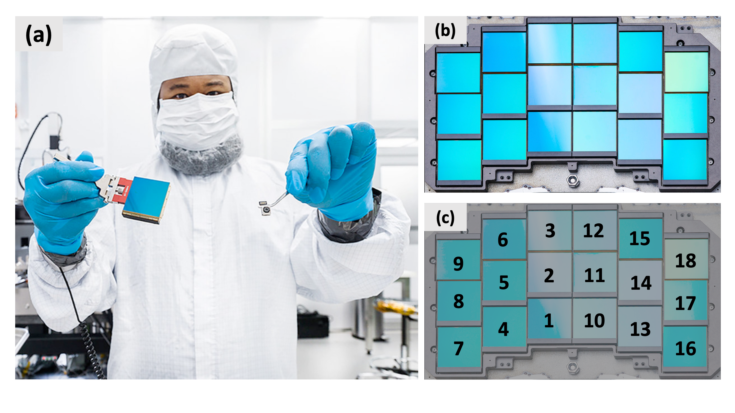
Panel (a) shows a WFI Team Member holding a single H4RG-10 detector on the left and comparing it to a typical cell phone camera for scale (Image Credit: NASA/Chris Gunn; Link to Original). Panel (b) shows the 18 H4RG-10 detectors that were integrated to form the Focal Plane Array (FPA) that permits the wide-field of view while maintaining the resolution (Image Credit: NASA/Chris Gunn; Link to Original). The detectors are arranged to minimize the overall wavefront error across the field. Panel (c) is identical to Panel (b) but shows the numbering system used for the individual detectors.
The Focal Plane Array on the Sky
The WFI detectors are arranged in the focal plane to form three rows of six detectors each that cover a roughly rectangular region on the sky. The columns are slightly offset from each other to minimize the overall wavefront error (the WFI focal plane is off-axis, see Coordinate Systems). Physical constraints force gaps between detectors; to minimize such gaps, the detectors are placed in two different orientations, so that the separation between rows is slightly different; namely, the detectors in the top two rows (positions 1, 4, 7, 10, 13, 16 and 2, 5, 8, 11, 14, 17) are placed "upside-down", with the low Y end at the top, while those in the third row (positions 3, 6, 9, 12, 15, 18) are placed top-up. This allows the gap between the second and third row to be smaller. However, the pixels will be rearranged in initial processing, so that all data have consistent X-Y orientations, with the same direction and sense for both axes, across all detectors. More detailed information about detector and telescope coordinate systems, including software utilities to perform transforms, can be found on the pySIAF for Roman for Roman article in the Simulation Tools Handbook.
The current optical modelling of the WFI suggests that the geometric distortion is small and amounts to less than 2% over the field of view. As a result, the pixel scale is nearly constant at 110 mas per pixel. This results in an outer dimension of the field of view of about 2800 arcsec by 1400 arcsec, including gaps; excluding gaps, the active area on the sky is 0.281 square degrees.
Readout and Reference Pixels
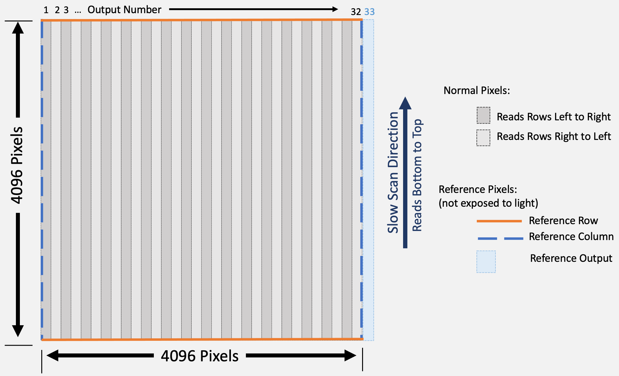
The specifics of the readout patterns and the reference pixels are critical to use of the H4RG-10. The Schematic of an H4RG-10 Detector provides context for the description to follow. Each detector is divided into 32 output regions that are 128 columns wide (with each column 4096 pixels long; these are shown by the vertical bands in the figure). Each output region is read by a separate amplifier and all 32 amplifiers operate in parallel. There are both fast and slow scan directions. The fast readout direction (along rows) switches its orientation every amplifier; odd-numbered amplifiers are read left to right, even-numbered right to left. The slow readout direction (along columns) is always read bottom to top. Each pixel readout takes 5 μs, so each 128-pixel row is read in about 640 μs (some additional cycles are needed when switching rows.) In addition, the readout switches regularly from normal pixels to guide window pixels, which also affects the detailed timing readout.
Fluctuations in the control and readout electronics can result in significant changes in the signal measured from the detector. As in previous generations of HgCdTe detectors, reference pixels are used to help measure and correct for such fluctuations. An H4RG-10 detector has both physical and virtual reference pixels. A 4-pixel wide border around the whole detector is disconnected from the light-sensitive layer and is therefore insensitive to light, but still experiences the same electronic effects as other pixels. The Schematic of an H4RG-10 Detector shows the reference rows (top and bottom) and columns (right and left) as dashed blue lines for columns and solid orange lines for rows. As a result, the total light-sensitive region of the detector is reduced to 4088 pixels by 4088 pixels (having removed 4 pixels on all four edges). The reference pixels provide a means to track the signal variations due to electronic fluctuations and are used for calibration. However, the left and right reference columns (dashed lines) are only read every 640 μs (the effective row readout time) where as the top and bottom reference rows are read only one time per detector readout. The H4RG-10 detectors also have an additional amplifier, often referred to as an additional (33rd) output channel (shown in light blue in the figure to the right of the 32nd output). This output reads a virtual reference pixel at the same cadence as the detector pixels. These reference data streams are combined to optimize the correction for readout fluctuations.
Schematic of an H4RG-10 Detector
The Relative Calibration System (RCS)
The science mission of the Roman telescope requires exquisite calibration and removal of detector and instrumental effects. To help this process, a sophisticated internal light source was devised known as the "Relative Calibration System" (RCS) (a simplified design from that presented in Wright et al. 2020) that serves as an internal calibration source.
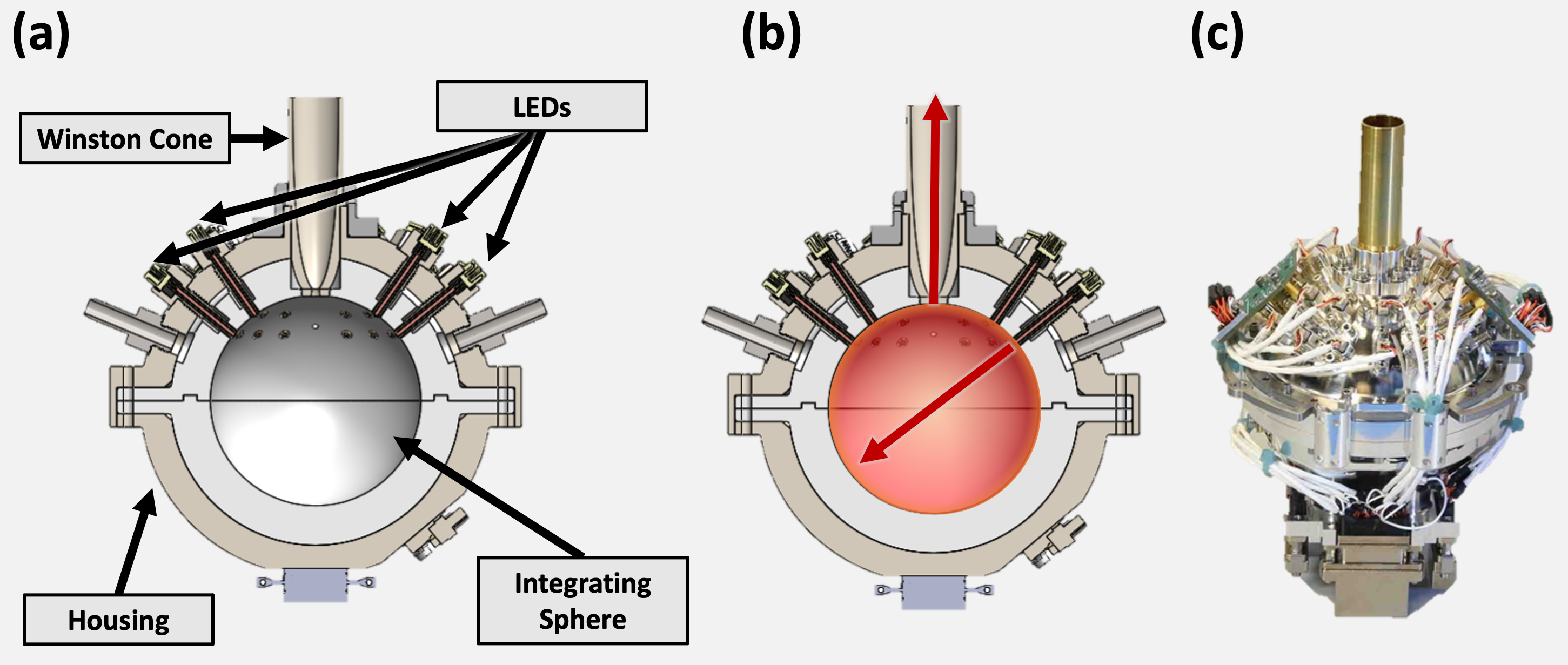
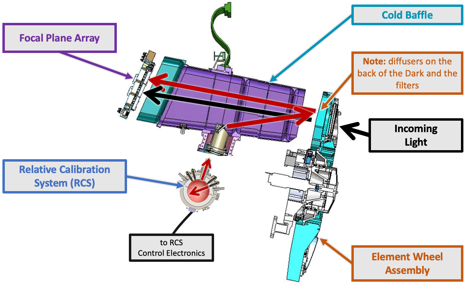
The Schematics of the Relative Calibration System provides an overview of its design and operation (panels a and b) and an image of the completed subsystem (panel c). The RCS works using banks of LEDs – each bank contains six LEDs and there are four banks for redundancy (two redundant sets on each of its "sides"). The LEDs shine light into an Integrating Sphere, which is a sphere of reflective surfaces that, in effect, diffuses the light from the LEDs. That light exits through a Winston Cone that helps to collect the light for projection into the focal plane. The Figure of the Light Path for the RCS demonstrates how the light from the RCS eventually makes it to the Focal Plane Array.
The RCS is capable of delivering several levels of light via LEDs at six different wavelengths. For each wavelength, two LEDs can be activated simultaneously at different brightness levels. The light from the RCS utilizes the diffusers on the back of the optical elements (Cromey et al. 2023). The purpose of creating these light sources is three-fold:
- By diffusing the light from the back of the dark element in the optical element wheel, the source can produce internal flats at six different wavelengths, each corresponding to the central wavelength of one of the broadband filters (no light source is available for F213). This allows creation of wavelength-dependent pixel-level flat fields, thus helping remove any residual pixel-to-pixel variation in color response.
- The source can produce different combinations of illumination in each band, by turning on one or two LEDs at different levels. Using the principle of light superposition, this process allows calibration of the linearity of the detectors for varying input flux levels (Count-Rate Dependent Non-Linearity or CRNL) to very high accuracy (better than 0.3%), without requiring any prior knowledge of the light output at each level; it is sufficient that each light output remain constant throughout the experiment.
- The source light can be reflected by the diffuser on the back of each filter to add light to an external science observation (dark red and black in the Schematics of the Relative Calibration System). Using the Lamp-on/Lamp-off (LOLO) method provides an alternate calibration of the count-rate dependent non-linearity.
Thus, the RCS can be operated in two ways: (1) it can provide Direct Illumination to the Focal Plane Array using the diffuser on the back of the Dark element for calibration and (2) it can be used in Lamp On/Lamp Off mode by illuminating the diffusers on the back of the filters. Deustua et al. (2021) provides a worked example for how the RCS impacts the accuracy of flux measurements for type Ia Supernovae.
Schematic of the Relative Calibration System (RCS)
Schematic of the Light Paths for the RCS
For additional questions not answered in this article, please contact the Roman Help Desk.
References
- Nancy Grace Roman Space Telescope webpage at STScI
- "Goddard Team Builds, Tests Calibrator for NASA’s Roman in Record Time", NASA Press Release 18 April 2023
- "RST Wide Field Instrument (WFI) Focal Plane Array Handbook", Cheung et al. 2025
Papers:
- "The ACADIA ASIC: detector control and digitization for the Wide-Field Infrared Survey Telescope (WFIRST)", Loose et al. 2018
- "Properties and characteristics of the WFIRST H4RG-10 detectors", Mosby et al. 2020
- “The WFI relative calibration system for WFIRST,” Wright et al. 2020
"The Roman Space Telescope Relative Calibration System and the Dark Energy Figure of Merit", Deustua et al. 2021
- "Reflective engineered diffusers on the Roman Space Telescope Wide Field Instrument", Cromey et al. 2023
- "Roman Wide Field Instrument Optomechanical Assembly performance summary", Cromey et al. 2025
- "Phase Retrieval in TVAC testing for the Roman Instrument", Valencia et al. 2025
- "Optical performance of Roman optical telescope assembly", Eegholm et al. 2025
- "Systems engineering integration and test of the wide field opto-mechanical assembly", Stewart et al. 2025